
Rotor for dual-rotor electric machine of hybrid power system

A hybrid power system and dual-rotor motor technology, which is applied to the layout of multiple different prime movers, power devices, and air pressure power devices of general power devices, can solve the problem of complex installation structures of dual-rotor motors that are unfavorable to the production of dual-rotor motors. Assembly and other issues, to achieve the effect of tight connection, convenient installation and fixing, and prevention of loss

Inactive Publication Date: 2020-11-10
江苏联博精密科技有限公司
View PDF0 Cites 0 Cited by
  • Summary
  • Abstract
  • Description
  • Claims
  • Application Information

AI Technical Summary

Problems solved by technology

[0002] The double-rotor motor is a kind of motor proposed by people in recent years. It is composed of two mechanical shafts and can realize the independent transmission of two mechanical energies. This new type of motor greatly reduces the volume and weight of the equipment and improves the working efficiency. , can well meet the requirements of energy saving and speed regulation, and has superior operating performance. Therefore, it has good application prospects in many fields. In the field of automotive hybrid power systems, the use of dual-rotor motors can consume fuel and power batteries at the same time The energy of the two sets of energy is mixed to improve the dynamic performance of the vehicle. The installation structure of the traditional dual-rotor motor is complicated, which is not conducive to the production and assembly of the dual-rotor motor.

Method used


Image

  • Rotor for dual-rotor electric machine of hybrid power system
  • Rotor for dual-rotor electric machine of hybrid power system
  • Rotor for dual-rotor electric machine of hybrid power system

Examples


Embodiment Construction

[0025] The following will clearly and completely describe the technical solutions in the embodiments of the present invention with reference to the accompanying drawings in the embodiments of the present invention. Obviously, the described embodiments are only some, not all, embodiments of the present invention. Based on the embodiments of the present invention, all other embodiments obtained by persons of ordinary skill in the art without making creative efforts belong to the protection scope of the present invention.

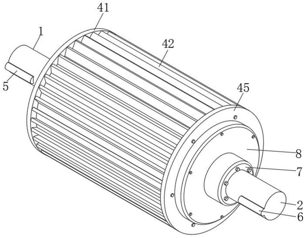
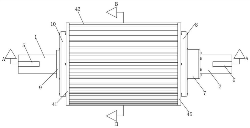
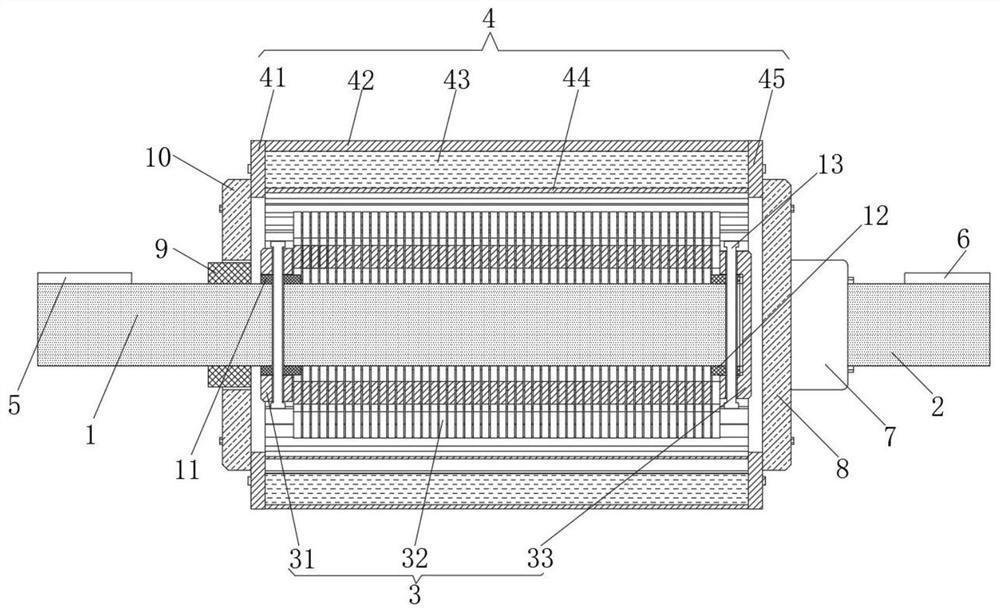
[0026] see Figure 1-4 , the present invention provides a technical solution: a rotor for a dual-rotor motor for a hybrid power system, including an inner shaft 1 and an outer shaft 2;

[0027] Inner shaft 1: the side of the left end is provided with a first bump 5, and the first bump 5 is a position-limiting structure, which is convenient for connection with an external device. The side of the inner shaft 1 is connected with a bearing 9 for rotation, and its ...


PUM

PropertyMeasurementUnit
Thicknessaaaaaaaaaa

Abstract

The invention discloses a rotor of a dual-rotor motor for a hybrid power system. The rotor comprises an inner shaft and an outer shaft, a first bump is arranged on the side surface of the left end part of the inner shaft, a bearing is rotatably connected to the side surface of the inner shaft, and an inner rotor is mounted on the side surface on the right side of the bearing; a second protruding block is arranged on the side face of the right end of the outer shaft, the left end of the outer shaft is connected with a fixed base, the left end of the fixed base is connected with a right fixing cover through a bolt, an outer rotor is fixed to the left end of the right fixing cover, the outer rotor is connected to the side face of the inner rotor in a sleeving mode, and a gap is reserved between the outer rotor and the inner rotor; the left end of the outer rotor is provided with a left fixed cover; a through hole corresponding to the bearing in position is formed in the middle of the leftfixing cover, and the bearing is installed in the through hole of the left fixing cover. The diameter of the inner shaft is equal to that of the outer shaft, and the double-rotor motor of the hybridpower system is simple in rotor installation mode and convenient to produce and assemble.

Description

technical field [0001] The invention relates to the technical field of dual-rotor motors, in particular to a rotor of a dual-rotor motor used in a hybrid power system. Background technique [0002] The double-rotor motor is a kind of motor proposed by people in recent years. It is composed of two mechanical shafts and can realize the independent transmission of two mechanical energies. This new type of motor greatly reduces the volume and weight of the equipment and improves the working efficiency. , can well meet the requirements of energy saving and speed regulation, and has superior operating performance. Therefore, it has good application prospects in many fields. In the field of automotive hybrid power systems, the use of dual-rotor motors can consume fuel and power batteries at the same time The energy of the two sets of energy is mixed to improve the dynamic performance of the vehicle. The installation structure of the traditional dual-rotor motor is complicated, whic...

Claims


Application Information

Patent Timeline
IPC IPC(8): H02K16/02H02K1/22H02K1/28H02K7/00B60K6/26
CPCB60K6/26H02K1/22H02K1/28H02K7/003H02K16/02
Inventor 肖庆朋饶志辉
Owner 江苏联博精密科技有限公司
Learn More