
Multi-body-position modular spinal cord injury rehabilitation robot mechanical structure

A rehabilitation robot and spinal cord injury technology, applied in passive exercise equipment, physical therapy, etc., can solve the problems of high participation of medical staff, large use demand, complicated operation, etc., and achieve the effect of improving space utilization and reducing vacant time

Active Publication Date: 2020-11-13
YANSHAN UNIV
View PDF13 Cites 4 Cited by
  • Summary
  • Abstract
  • Description
  • Claims
  • Application Information

AI Technical Summary

Problems solved by technology

[0003] At this stage, the equipment developed by various institutions is constantly improving, and there are many types of rehabilitation equipment on the market, but there are still some deficiencies, which can be summarized as follows: 1. These equipment are low in automation, complicated in operation, and require a high degree of participation of medical staff, which is not suitable for intelligent The social development direction of medical care; 2. The full-stage rehabilitation of patients requires different rehabilitation training programs and targeted rehabilitation equipment. Most rehabilitation equipment has a single rehabilitation site and cannot meet individual needs; 4. These devices can only be used by a single person in the same period of time, and cannot meet the scenarios where there are many patients and large usage needs

Method used


Image

  • Multi-body-position modular spinal cord injury rehabilitation robot mechanical structure
  • Multi-body-position modular spinal cord injury rehabilitation robot mechanical structure
  • Multi-body-position modular spinal cord injury rehabilitation robot mechanical structure

Examples


Embodiment Construction

[0052] Below in conjunction with embodiment the present invention is described in further detail:

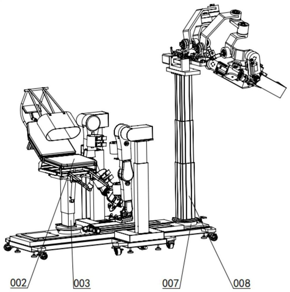
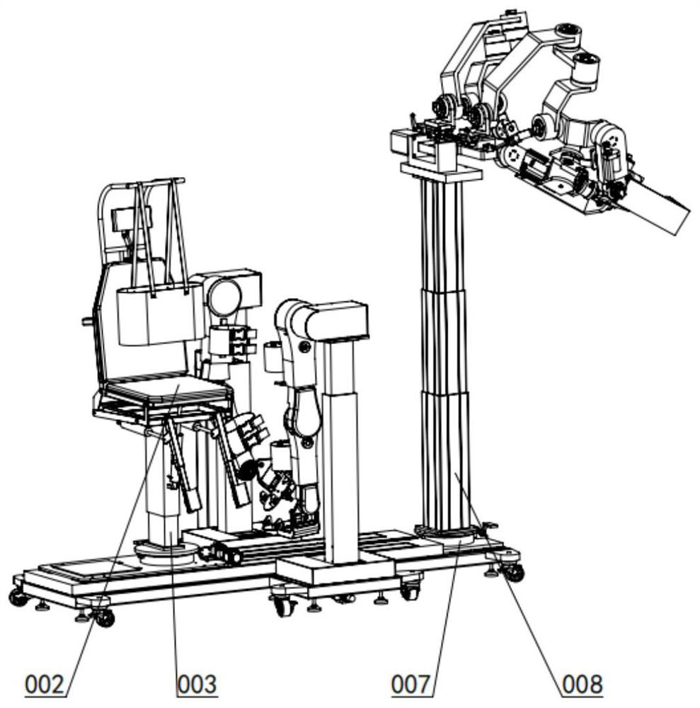
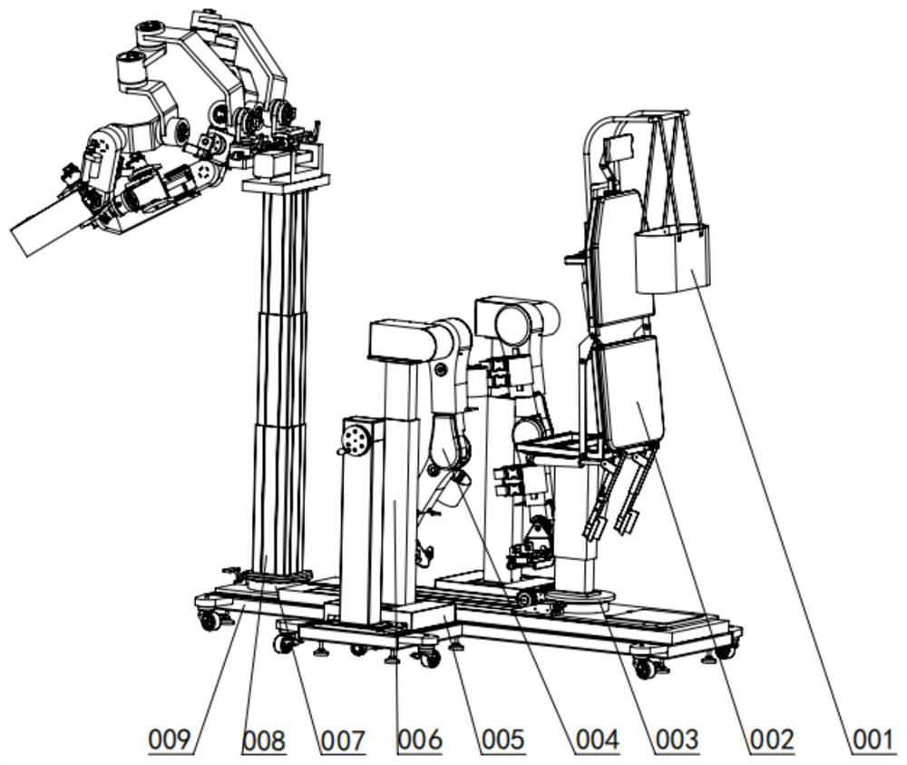
[0053] A mechanical structure of a multi-position modular spinal cord injury rehabilitation robot, including a "ten"-shaped underframe structure assembly 009, a seat base assembly 003, an upper limb rehabilitation system base assembly 007, and two left and right sides of the seat base assembly 003. A lower limb rehabilitation system base assembly 005 is detachably arranged in the shape of a "ten" above the chassis structure assembly 009, and a seat assembly 002 is arranged above the seat base assembly 003, and the seat assembly 003 can be adjusted to achieve different postures. The height adjustment, linear movement and functional rotation of the seat assembly 002, the human body weight adjustment assembly 001 is arranged behind the back of the seat assembly 002, and the upper limb rehabilitation system exoskeleton assembly 008 is arranged above the upper limb rehabilitation syst...


PUM


Abstract

The invention discloses a multi-body-position modular spinal cord injury rehabilitation robot mechanical structure. A human body load adjusting assembly changes the telescopic amount of a cantilever beam electric push rod by detecting the numerical value of a plantar pressure sensor so as to adjust the height of a cantilever beam for human body load training. A seat base assembly achieves linear movement through gear and rack transmission, 90-degree rotation is achieved through rotation supporting and limiting, and height adjustment is achieved through the seat lifting table. A lower limb rehabilitation system base assembly is provided with a manual adjusting lead screw for rotating and adjusting the distance between lower limb rehabilitation systems. An upper limb rehabilitation system base assembly achieves 180-degree rotation through rotation supporting and limiting. An underframe structure assembly is in a cross-shaped frame shape. The multi-body-position requirements of patients in different rehabilitation stages can be met, the modular design meets the requirement that two patients conduct safe and efficient rehabilitation training at the same time, the scenes with many patients and large use requirements are met, the automation degree is high, operation is easy, the participation degree of medical staff is low, and the structure is suitable for the social development direction of intelligent medical treatment.

Description

technical field [0001] The invention relates to the technical field of medical rehabilitation equipment, in particular to a mechanical structure of a multi-position modular spinal cord injury rehabilitation robot. Background technique [0002] In recent years, industrial, mining and traffic accidents have occurred more and more frequently, and there are more and more patients with spinal cord injuries. Spinal cord injuries are high in young adults aged 16-30, which not only brings catastrophic physical and psychological blows to individuals, but also to their families. and a heavy burden on society. In order to relieve social medical pressure, many scientific research institutes and enterprises have vigorously developed spinal cord injury rehabilitation robots, and are committed to reducing the work intensity of medical staff and improving the rehabilitation effect of patients. For the comparative study on the rehabilitation of patients with spinal cord injury, it has been ...

Claims


Application Information

Patent Timeline
Patent Type & Authority Applications(China)
IPC IPC(8): A61H1/00A61H1/02
CPCA61H1/005A61H1/0237A61H1/024A61H1/0244A61H1/0266A61H1/0274A61H2201/1207A61H2201/1463A61H2201/1633A61H2201/1638A61H2201/1642A61H2201/5071
Inventor 边辉孙朝亮丁杰彬李佳辰李帅
Owner YANSHAN UNIV
Learn More