
Energy-saving type automobile stamping part antirust liquid recycling mechanism

A technology of automobile stamping parts and recycling mechanism, which is applied in the direction of solid waste removal, liquid cleaning method, cleaning method and utensils, etc. It can solve the problem that anti-rust oil contains harmful substances, the ground is difficult to remove, anti-rust oil falls, etc. problem, achieve the effect of saving production cost and environmental treatment cost, and preventing falling inside the machine

Inactive Publication Date: 2020-11-13
尤文静
View PDF6 Cites 0 Cited by
  • Summary
  • Abstract
  • Description
  • Claims
  • Application Information

AI Technical Summary

Problems solved by technology

[0002] Automotive stamping parts are produced by applying external force to plates, strips, pipes and profiles by presses and molds to cause plastic deformation or separation, and automotive stamping parts will have residual stamping oil after processing. It plays an anti-rust role for automobile stamping parts, but usually the anti-rust oil falls into the ground and is discharged into the pipeline, or volatilizes on the ground. There are substances in the anti-rust oil that are harmful to human health. For modern mold factories, anti-rust Liquid recovery is a serious problem in modern production
[0003] The common way to clean the anti-rust liquid is to wash it with water, but it will cause stains that are difficult to remove on the ground, and it needs to be discharged into the sewer after washing, which pollutes the environment and increases the production cost in disguise. Oil contains harmful substances, and the recycling method must play a role in ensuring human safety

Method used


Image

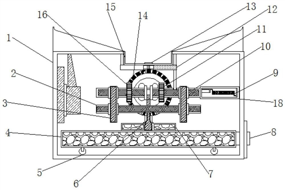
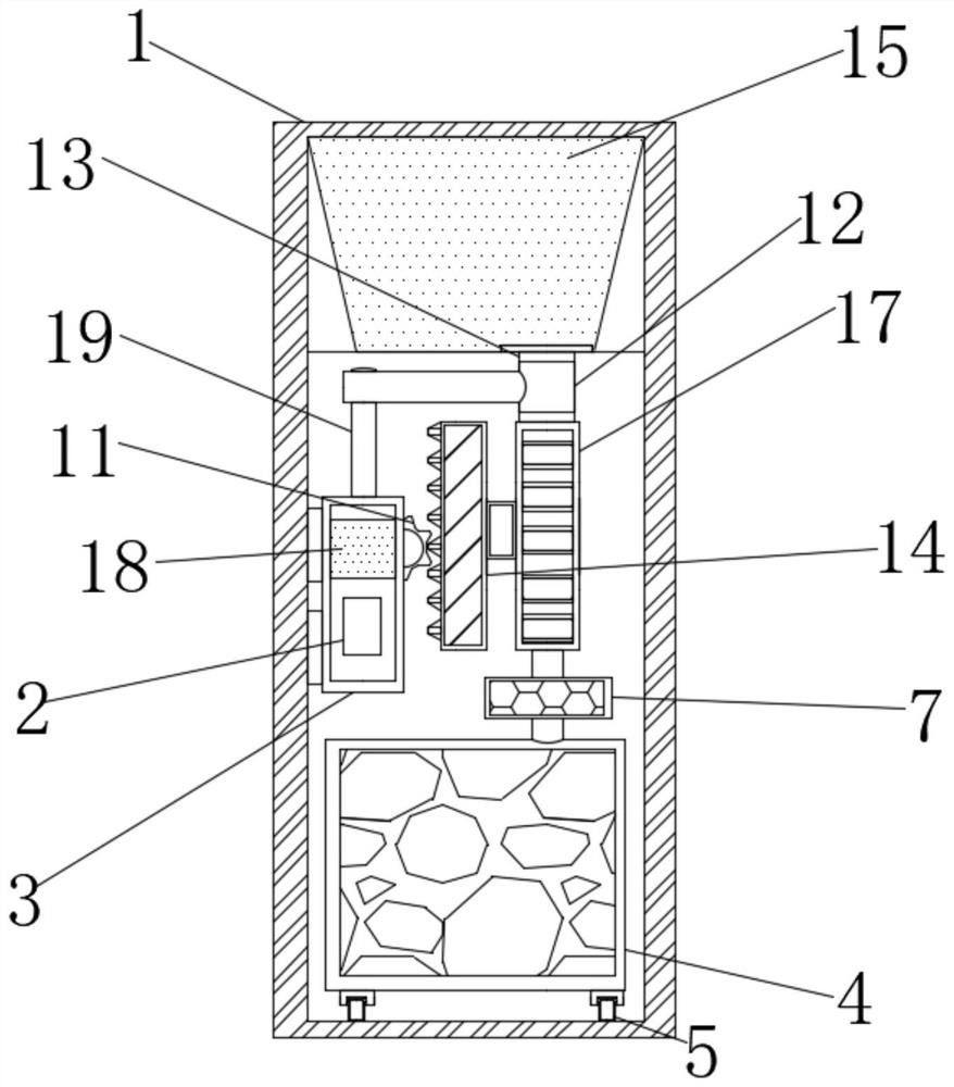
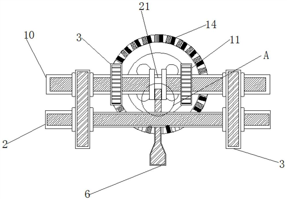
  • Energy-saving type automobile stamping part antirust liquid recycling mechanism
  • Energy-saving type automobile stamping part antirust liquid recycling mechanism
  • Energy-saving type automobile stamping part antirust liquid recycling mechanism

Examples


Embodiment Construction

[0021] The following will clearly and completely describe the technical solutions in the embodiments of the present invention with reference to the accompanying drawings in the embodiments of the present invention. Obviously, the described embodiments are only some, not all, embodiments of the present invention. Based on the embodiments of the present invention, all other embodiments obtained by persons of ordinary skill in the art without making creative efforts belong to the protection scope of the present invention.

[0022] see Figure 1-6 , an energy-saving anti-rust liquid recovery mechanism for automobile stamping parts, including a mechanism casing 1, a second gear 14, a liquid collecting tank 15 is provided on the top of the mechanism casing 1, and the top of the mechanism casing 1 is fixedly connected with a liquid collecting groove 15 The water inlet 13, the center of the mechanism shell 1 is fixedly connected with the water outlet tank 17, the right side of the mec...


PUM


Abstract

The invention relates to the technical field of antirust liquid recycling and provides an energy-saving type automobile stamping part antirust liquid recycling mechanism which comprises a mechanism shell and a second gear; a liquid gathering groove is formed in the top end of the mechanism shell; a water inlet is fixedly connected with the top of the mechanism shell through the liquid gathering groove; and a water outlet tank is fixedly connected with the center of the mechanism shell. When the energy-saving type automobile stamping part antirust liquid recycling mechanism is full of antirustliquid, a spring drives a second push rod to do rightward linear motion; the second push rod drives a baffle plate to do rightward linear motion; the baffle plate drives a third connecting rod to do leftward linear motion; the third connecting rod drives a sealing rod to do leftward linear motion; and the sealing rod blocks antirust liquid flowing out of a water inlet, so that when a liquid storage tank is transported out for application, liquid does not fall into the mechanism shell and is prevented from falling into a machinery, and the inner side of the machinery is not polluted.

Description

technical field [0001] The invention relates to the technical field of anti-rust liquid recovery, in particular to an anti-rust liquid recovery mechanism for energy-saving automobile stamping parts. Background technique [0002] Automotive stamping parts are produced by applying external force to plates, strips, pipes and profiles by presses and molds to cause plastic deformation or separation, and automotive stamping parts will have residual stamping oil after processing. It plays an anti-rust role for automobile stamping parts, but usually the anti-rust oil falls into the ground and is discharged into the pipeline, or volatilizes on the ground. There are substances in the anti-rust oil that are harmful to human health. For modern mold factories, anti-rust Liquid recovery is a serious problem in modern production. [0003] The common way to clean the anti-rust liquid is to wash it with water, but it will cause stains that are difficult to remove on the ground, and it needs...

Claims


Application Information

Patent Timeline
Patent Type & Authority Applications(China)
IPC IPC(8): B08B3/02B08B13/00B09B3/00
CPCB08B3/02B08B13/00B09B3/00
Inventor 尤文静
Owner 尤文静
Learn More