Sampling test tube cleaning equipment for clinical laboratory urine examination

A technology for cleaning equipment and laboratory, applied in the field of sampling test tube cleaning equipment for urine testing in laboratory, can solve the problems of low work efficiency, complicated operation, labor-intensive and other problems, and achieve the effect of improving work efficiency, simple operation and saving labor.

Pending Publication Date: 2020-11-13
黄永英
View PDF0 Cites 3 Cited by
  • Summary
  • Abstract
  • Description
  • Claims
  • Application Information

AI Technical Summary

Problems solved by technology

[0006] In order to overcome the disadvantages of cumbersome operation, low work efficiency, and relatively labor-intensive operation in the above-mentioned method, the technical problem to be solved by the present invention is to provide an inspection machine that is simple to operate, can improve work efficiency, and saves manpower. Sampling test tube cleaning equipment for urine test

Method used


Image

  • Sampling test tube cleaning equipment for clinical laboratory urine examination
  • Sampling test tube cleaning equipment for clinical laboratory urine examination
  • Sampling test tube cleaning equipment for clinical laboratory urine examination

Examples


Embodiment 1

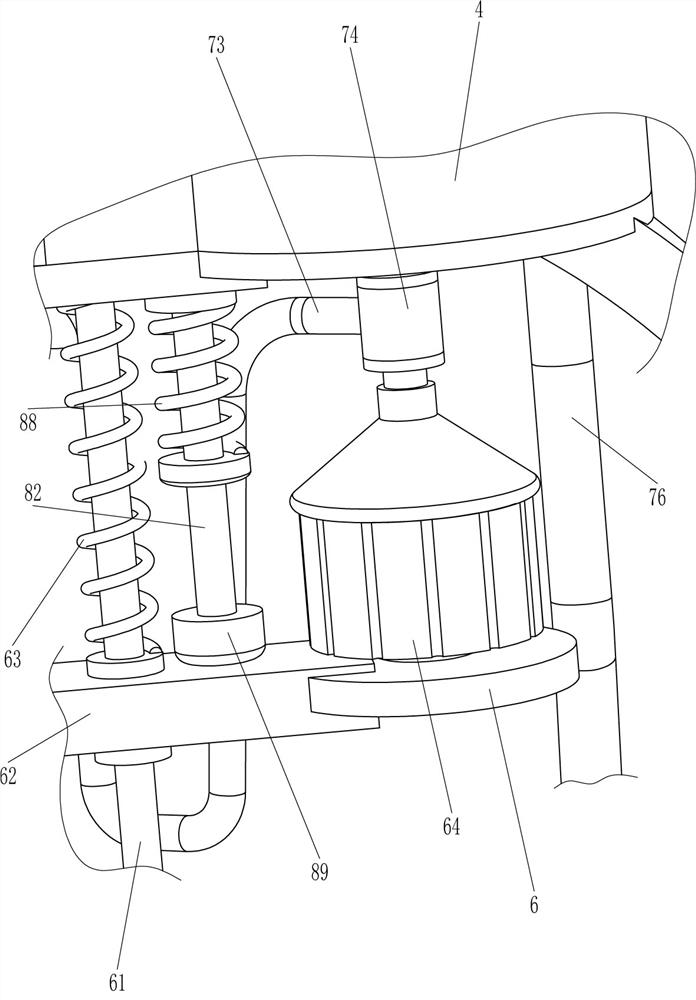
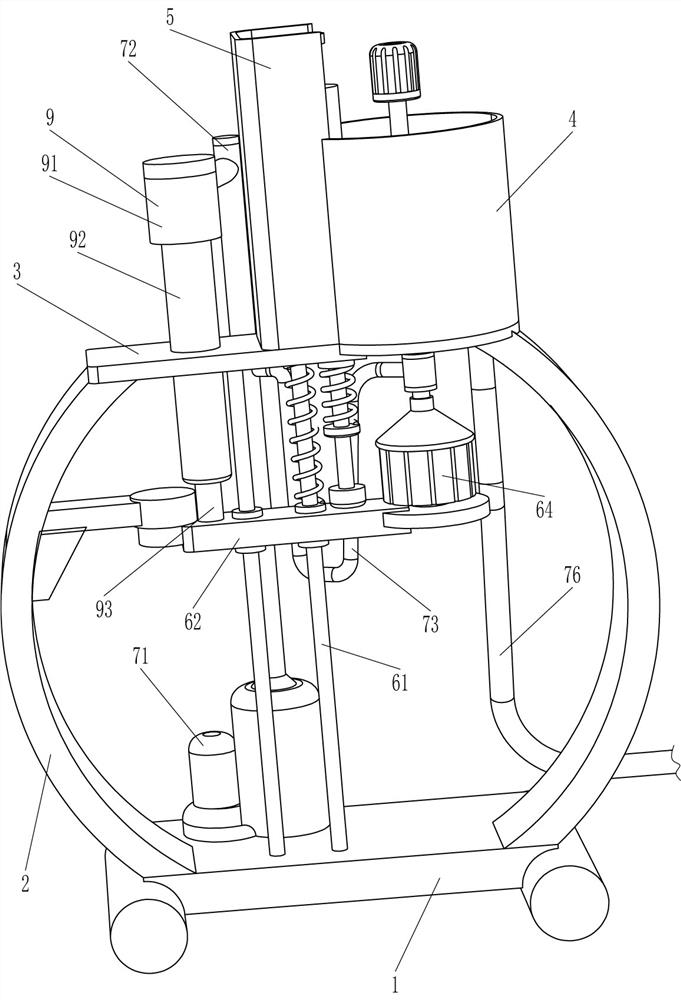
[0026] A kind of sampling test tube cleaning equipment for laboratory urine test, such as Figure 1-4 As shown, it includes a support 1, an arc plate 2, a mounting plate 3, a water collection frame 4 and a water retaining groove 5. The left and right sides of the top of the support 1 are connected with the arc plate 2, and the top of the arc plate 2 on both sides A mounting plate 3 is connected between them, a water collection frame 4 is connected to the top right side of the mounting plate 3, a water retaining groove 5 is connected between the left side of the water collection frame 4 and the mounting plate 3, and a cleaning mechanism 6 and a water injection mechanism 7 are also included. A cleaning mechanism 6 is provided between the seat 1 and the mounting plate 3 , and a water injection mechanism 7 is provided between the support 1 and the cleaning mechanism 6 .

[0027] The cleaning mechanism 6 includes a slide bar 61, a slide plate 62, a first spring 63, a driving motor ...

Embodiment 2

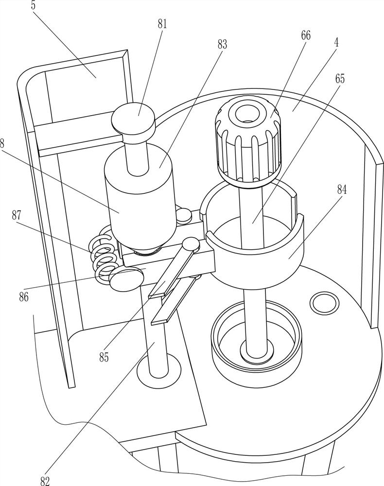
[0031] On the basis of Example 1, such as figure 2 and Figure 4 As shown, a clamping mechanism 8 is also included, and the clamping mechanism 8 includes a baffle plate 81, a sliding rod 82, a tapered column 83, a clamp ring 84, a hinged rod 85, an arc contact plate 86, a second spring 87, a second Three springs 88 and a contact block 89, the upper part of the water retaining tank 5 is connected with a baffle 81, the right side of the mounting plate 3 is slidably connected with a sliding rod 82, the baffle 81 is used to limit the sliding rod 82, and the upper part of the sliding rod 82 is connected There is a tapered column 83, and the front and rear walls of the water retaining tank 5 are connected with hinged rods 85, the hinged rods 85 are hingedly connected with arc contact plates 86, and the arc contact plates 86 are connected with clamp rings 84, and the two arc contacts The second spring 87 is connected between the plates 86, the tapered column 83 cooperates with the ...

Embodiment 3

[0034] On the basis of Example 2, such as figure 1 As shown, a push mechanism 9 is also included. The push mechanism 9 includes a water sleeve 91, a piston pipe 92 and a push rod 93. The top of the vertical pipe 72 is connected with a water sleeve 91, and the water sleeve 91 communicates with the vertical pipe 72. The water jacket 91 is connected with a piston tube 92 , the piston tube 92 passes through the mounting plate 3 , and a push rod 93 is slidably connected in the piston tube 92 , and the bottom of the push rod 93 is connected with the slide plate 62 .

[0035]The water ejected in the standpipe 72 is also injected into the piston tube 92 through the water receiving sleeve 91, more and more water in the piston tube 92 can push the push rod 93 to move downward, and the push rod 93 moves downward to push the slide plate 62 downward. Move, like this, just do not need manually to push slide plate 62 to move downwards, effectively saved manpower.

[0036] like Figure 5 As...


PUM


Abstract

The invention relates to cleaning equipment, in particular to sampling test tube cleaning equipment for clinical laboratory urine examination. The technical problem to be solved by the invention is how to design the sampling test tube cleaning device for laboratory urine examination, which is simple to operate, and capable of improving working efficiency and saving manpower. In order to solve thetechnical problem, the sampling test tube cleaning equipment for clinical laboratory urine examination comprises a support, a mounting plate, a water collecting frame, a cleaning mechanism and a waterinjection mechanism, wherein two sides of the top of the support are connected with arc plates; the mounting plate is connected between the tops of the arc-shaped plates on the two sides; the water collecting frame is connected to one side of the top of the mounting plate, and a water blocking groove is connected between the water collecting frame and the mounting plate; the cleaning mechanism isarranged between the support and the mounting plate; and the water injection mechanism is arranged between the support and the cleaning mechanism. According to the sampling test tube cleaning equipment for clinical laboratory urine examination, a test tube is cleaned through the cooperation operation of the cleaning mechanism and the water injection mechanism, so that the effect of cleaning the test tube is achieved.

Description

technical field [0001] The invention relates to a cleaning device, in particular to a cleaning device for sampling test tubes used in laboratory urine testing. Background technique [0002] Test tube, a commonly used instrument in chemical laboratories, is used as a reaction container for a small amount of reagents. It is used at room temperature or when heated (it should be preheated before heating, otherwise the test tube is easy to burst.). Test tubes are divided into ordinary test tubes, support test tubes, centrifuge test tubes and so on. When testing urine in the laboratory, it is usually necessary to use a test tube. After the test tube is used, the inside of the test tube usually needs to be cleaned to prevent the internal urine from remaining for a long time to breed bacteria and easily cause infection to the user. [0003] At present, the way to clean the test tube is usually to manually insert the cleaning brush into the test tube, then pour water into the test t...

Claims


Application Information

Patent Timeline
IPC IPC(8): B08B9/28B08B9/34B08B13/00
CPCB08B9/0813B08B9/28B08B9/34B08B13/00
Inventor 黄永英
Owner 黄永英
Why Eureka
Try Eureka