Armed rotor wing drone attitude control method aiming at centroid shift and base floating

A multi-rotor unmanned aerial vehicle and unmanned rotor technology, which is applied in attitude control, non-electric variable control, control/regulation system, etc., can solve the problems of poor accuracy and rapidity, aircraft dynamics stability and accuracy, Without considering the center of mass offset interference and other issues, it achieves the effect of increasing stability and quick response ability, comprehensive stability and operation error analysis, and wide engineering applicability

Active Publication Date: 2020-11-13
BEIHANG UNIV
View PDF10 Cites 13 Cited by
  • Summary
  • Abstract
  • Description
  • Claims
  • Application Information

AI Technical Summary

Problems solved by technology

[0004] The patent application number is CN201720515134.6, which proposes a flying manipulator with a flexible gripper. With the help of the rapid movement of the multi-rotor aircraft, the success rate of the flexible gripper's grasping task is improved, but there are two problems: (1) The patent does not consider the center of mass offset interference caused by the movement of the multi-degree-of-freedom robotic arm, which will affect the dynamic stability and accuracy of the aircraft; (2) The error of the base floating on the gripper is not considered transmission, will be greatly limited in practical use
The patent application number is CN201721229966.8, which proposes a grabbing operation-oriented rotor flying manipulator system, which also has similar problems: (1) The interference caused by the offset of the center of mass is not considered; (2) The base is not considered in the method The impact of floating on the end effector cannot guarantee the accuracy of the operation, so it will be weaker than the method proposed in this patent in terms of accuracy and rapidity.

Method used


Image

  • Armed rotor wing drone attitude control method aiming at centroid shift and base floating
  • Armed rotor wing drone attitude control method aiming at centroid shift and base floating
  • Armed rotor wing drone attitude control method aiming at centroid shift and base floating

Examples


Embodiment Construction

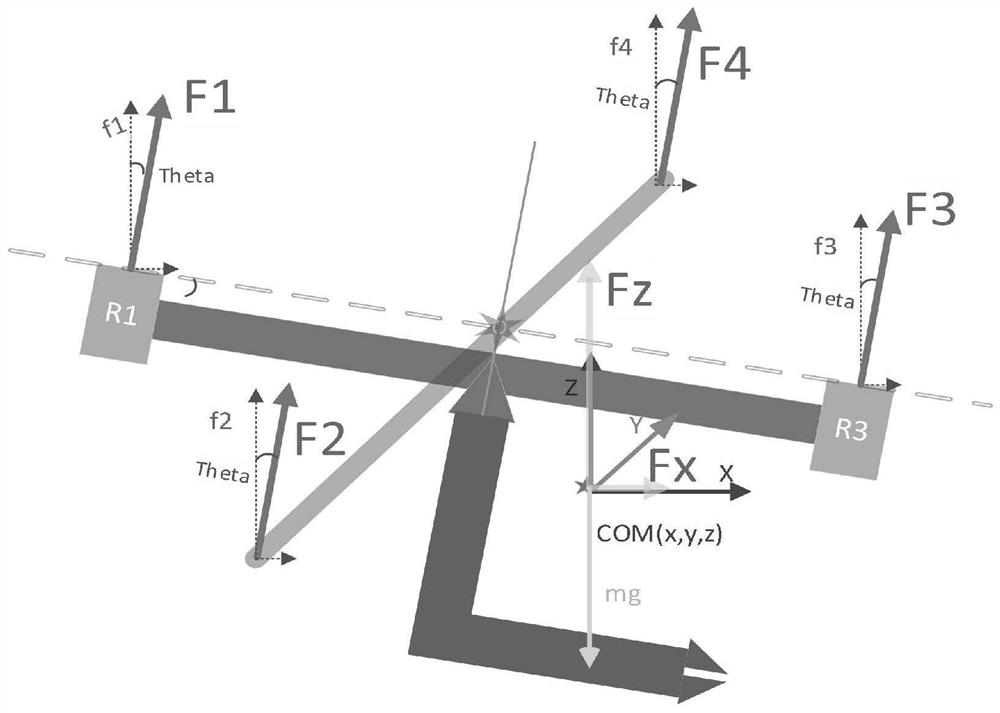
[0048] Taking a general-purpose rotor UAV flight system with multi-degree-of-freedom manipulator as an example to illustrate the specific implementation of the system and method, the flying manipulator has high requirements for attitude control accuracy and stability during the hovering work phase;

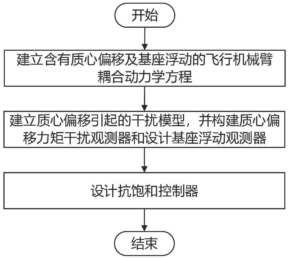
[0049] Such as figure 2 Shown, the specific implementation steps of the present invention are as follows:

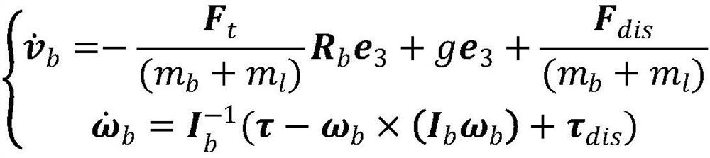
[0050] 1. Aiming at the common center of mass offset and base floating characteristics of the rotor flying manipulator, and considering the dynamic equations of the rotor UAV and the multi-degree-of-freedom manipulator, the dynamic model of the rotor flying manipulator is established, expressed as follows:

[0051]

[0052] In the formula, v b Indicates the translational velocity of the rotor UAV as the base of the manipulator, m b and m l are the masses of the multi-rotor UAV and the manipulator, respectively; F t is the total thrust of the multi-rotor UAV, R b is ...


PUM


Abstract

The invention relates to an armed rotor wing drone attitude control method aiming at centroid shift and base floating. The method comprises the following steps of aiming at the influence of centroid shift and base floating on the tail end control precision of a mechanical arm, firstly, constructing a flying mechanical arm kinetic equation containing centroid shift and base disturbance; secondly, indirectly controlling the drone by configuring different joints of the multi-degree-of-freedom mechanical arm according to the dynamic influence of centroid shift on the drone of the rotor wing with the arm; aiming at disturbance caused by base floating, designing a base floating disturbance observer to estimate the amplitude of the base floating disturbance observer; designing an anti-saturationcontroller for inhibiting aiming at the floating interference observation error of the base; and designing an anti-interference controller, and completing anti-interference attitude control over the flying mechanical arm under the multi-source interference condition. According to the method, the attitude control precision of the armed rotor drone can be remarkably improved, the method can be applied to the fields of security and protection, industry, military affairs and the like, and the high-precision attitude control requirement of the armed rotor drone in the special operation processes ofobject grabbing, transportation, dangerous object removal and the like is met.

Description

technical field [0001] The present invention relates to an attitude control method for the center of mass offset and base floating of an unmanned aerial vehicle with an arm, which is applicable to the weight of less than 25 kg or the size of any dimension not greater than 10 meters, equipped with a multi-degree-of-freedom mechanical arm and needs to achieve high The invention discloses a precision-controlled rotor drone attitude control system, which belongs to the field of aircraft attitude control. Background technique [0002] In recent years, UAV technology has been widely used in remote sensing, reconnaissance, plant protection, logistics, inspection and other fields. However, as the complexity of tasks continues to increase, the task requirements become more and more difficult. At the same time, drones need to be equipped with sensors with more diverse functions to enhance their own perception capabilities. In addition, with the increase in the types of drone missions...

Claims


Application Information

Patent Timeline
Patent Type & Authority Applications(China)
IPC IPC(8): B25J9/16G05D1/08G05D1/10
CPCB25J9/1605B25J9/1664G05D1/0825G05D1/101
Inventor 余翔吕尚可刘钱源郭雷乔建忠
Owner BEIHANG UNIV
Why Eureka
Try Eureka