Plate punching device for furniture manufacturing

A technology of punching device and plate, applied in fixed drilling machine and other directions, can solve the problems of high labor intensity, reduce punching efficiency, easy arm soreness, etc., and achieve the effect of reducing labor intensity and improving punching efficiency.

Active Publication Date: 2020-11-13
山东凯迪威家具有限公司
View PDF6 Cites 9 Cited by
  • Summary
  • Abstract
  • Description
  • Claims
  • Application Information

AI Technical Summary

Problems solved by technology

[0005] In order to overcome the disadvantages that the manual hand-held electric drill punches holes in the plate, the arm is easy to be sore, the labor intensity is relatively high, and the punching efficiency will be reduced. Hole-efficient panel punching device for furniture making

Method used


Image

  • Plate punching device for furniture manufacturing
  • Plate punching device for furniture manufacturing
  • Plate punching device for furniture manufacturing

Examples


Embodiment 1

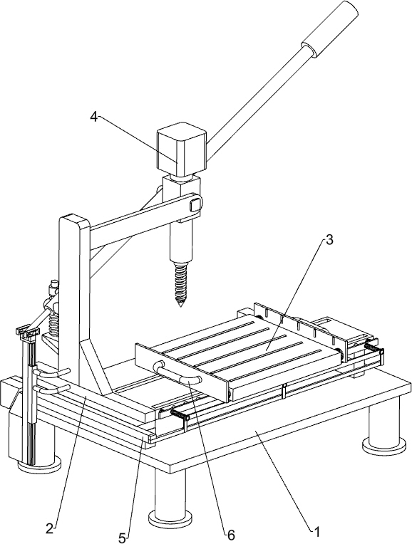
[0022] A kind of board punching device for making furniture, such as Figure 1-5 As shown, it includes a base plate base 1, a mounting frame 2, a plate moving mechanism 3 and a punching mechanism 4, and the left side of the top of the base plate base 1 is connected with a mounting frame 2, and the base plate base 1 is equipped with a plate moving mechanism 3. On the mounting frame 2 A punching mechanism 4 is installed.

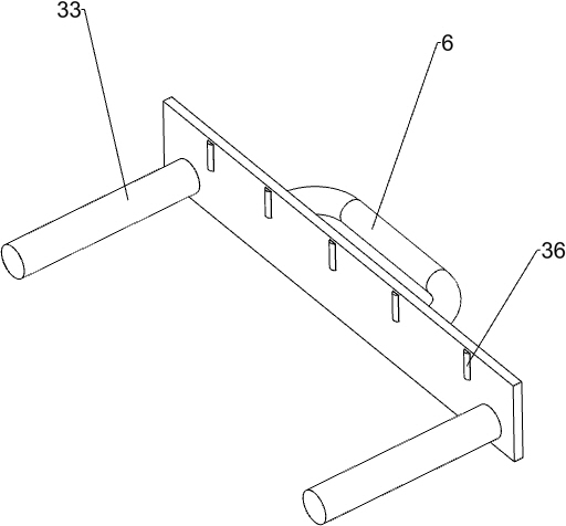
[0023] The plate moving mechanism 3 includes a grooved guide rail plate 31, a sliding pallet 32, a sliding side plate 33, a first back-moving spring 34, a first sliding shaft 35 and a second sliding shaft 36, and the right side of the top of the base seat 1 and the mounting frame 2. A slotted guide rail plate 31 is connected between the sides, and a sliding supporting plate 32 is slidably connected on the slotted guiding rail plate 31. The left and right sides of the sliding supporting plate 32 are all slidingly connected with a sliding side plate 33, and the ...

Embodiment 2

[0027] On the basis of Example 1, such as Figure 1-3 and Figure 5 As shown, a lateral movement locking mechanism 5 is also included, and the lateral movement locking mechanism 5 includes a T-shaped bar 51, a sliding frame 52, a fixed limit guide rail 53, a first wedge block 54, a second wedge block 55, and a sliding connection frame 56 , the second fixed guide rail plate 57, the sliding coupling frame 58, the fixed guide rod 59, the clamping frame 510, the third return spring 511 and the fourth return spring 512, the left side of the installation frame 2 is connected with a fixed limit guide rail 53, fixed The limit guide rail 53 is slidably connected with a sliding frame 52, and the upper part of the sliding frame 52 is slidably connected with a T-shaped bar 51. Block 54, the mounting frame 2 is embedded with a second fixed guide rail plate 57, the second fixed guide rail plate 57 is slidably connected with a sliding connection frame 56, and the rear side of the sliding co...


PUM


Abstract

The invention relates to a plate punching device, and particularly relates to a plate punching device for furniture manufacturing. The plate punching device for furniture manufacturing can reduce thelabor intensity of workers and improve the punching efficiency. The plate punching device for furniture manufacturing comprises a bottom plate base, a plate moving mechanism and a punching mechanism,wherein a mounting frame is connected to the bottom plate base, the plate moving mechanism is arranged on the bottom plate base, and the punching mechanism is arranged on the mounting frame. Accordingto the plate punching device, the punching mechanism can punch a plate on the plate moving mechanism, the plate can be conveniently moved through the plate moving mechanism, and therefore the punching mechanism can punch all positions of the plate, the plate does not need to be punched by manually holding an electric drill for a long time, and the effects of reducing the labor intensity of the workers and improving the punching efficiency are achieved.

Description

technical field [0001] The invention relates to a plate punching device, in particular to a plate punching device for making furniture. Background technique [0002] The boards need to be drilled before they can be spliced ​​into various furniture. At present, manual hand-held electric drills are generally used to punch the boards. However, due to the heavy weight of the electric drill, the arm of the hand-held electric drill for a long time is prone to soreness and labor intensity. Reduce drilling efficiency. [0003] Therefore urgently need to develop a kind of board punching device that can reduce the labor intensity of workman, can improve punching efficiency for furniture making. Contents of the invention [0004] (1) Technical problems to be solved [0005] In order to overcome the disadvantages that the manual hand-held electric drill punches holes in the plate, the arm is easy to be sore, the labor intensity is relatively high, and the punching efficiency will be...

Claims


Application Information

Patent Timeline
Patent Type & Authority Applications(China)
IPC IPC(8): B27C3/02
CPCB27C3/02
Inventor 彭子琪
Owner 山东凯迪威家具有限公司
Why Eureka
Try Eureka