A vacuum low-temperature continuous drying method and equipment for municipal sludge

A municipal sludge, vacuum and low temperature technology, applied in separation methods, sludge treatment, chemical instruments and methods, etc., can solve the problems of inability to realize green production, low drying efficiency, high heat source cost, etc., and achieve simple structure and high drying efficiency High, uniform cloth effect

Active Publication Date: 2020-12-11
青岛诺亚方舟环境工程有限公司潍坊分公司
View PDF8 Cites 2 Cited by
  • Summary
  • Abstract
  • Description
  • Claims
  • Application Information

AI Technical Summary

Problems solved by technology

However, the existing municipal sludge high-temperature thermal drying process also has some disadvantages: complex equipment, low drying efficiency, high heat source cost, and cannot achieve green production

Method used


Image

  • A vacuum low-temperature continuous drying method and equipment for municipal sludge
  • A vacuum low-temperature continuous drying method and equipment for municipal sludge
  • A vacuum low-temperature continuous drying method and equipment for municipal sludge

Examples


Embodiment 1

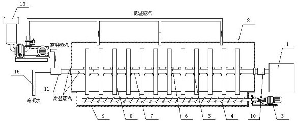
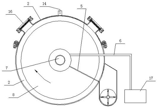
[0048] as attached figure 1 , 2 , 7, a kind of municipal sludge vacuum low-temperature continuous drying equipment of the present invention, its structure includes a relatively sealed drying shell 2, the drying shell 2 is provided with a horizontal rotating shaft 7, and a heating plate 8 is installed on the horizontal rotating shaft 7 , the heating plate 8 has a certain roughness, which is convenient for municipal sludge distribution. The side of the heating plate 8 is provided with a cloth assembly 6 and a scraper 5. The cloth assembly 6 and the scraper 5 are fixed on the drying shell 2. The inlet of the cloth assembly 6 is The pipe section is connected to the municipal sludge silo, and the outlet pipe section is provided with a municipal sludge outlet. Driven by the horizontal rotating shaft 7, the relative rotation occurs between the heating plate 8 and the cloth assembly 6 to lay the municipal sludge on the heating plate 8. on the disk;

[0049] The horizontal rotating s...

Embodiment 2

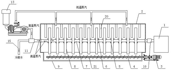
[0064] as attached Figure 1-4 , 7, on the basis of Embodiment 1, a semicircular heat radiation plate 20 is provided on the left and right sides of the upper half of the heating plate 8, the heat radiation plate 20 is a hollow structure, and the heat radiation plate 20 The arc surface is arranged on the inner wall of the arc drying shell 2 . The screw seal discharge assembly includes a U-shaped discharge casing 9, a discharge motor 3 and a discharge screw shaft 4 that is arranged in the U-shaped discharge casing 9 and connected with the discharge motor 3, and the discharge screw shaft 4 is provided with There are helical blades 21 . One or more of the discharge screw shaft 4, the screw blade 21 or the U-shaped discharge shell 9 is a hollow structure, and a heating medium passes through it.

Embodiment 3

[0066] as attached figure 1 , 2 , 4, 5, and 7, with reference to Embodiment 1 and Embodiment 2, only a semicircular heat radiation plate 20 is provided on the left and right sides of the upper half of the heating plate 8, and the heat radiation plate 20 is hollow structure, the arc-shaped surface of the heat radiation plate 20 is arranged on the inner wall of the arc-shaped drying shell 2 .


PUM


Abstract

The invention provides a municipal sludge vacuum low-temperature continuous drying method and equipment. The invention belongs to the technical field of sludge drying treatment. The drying method is based on municipal sludge continuous drying equipment. The equipment comprises a relatively sealed drying shell for drying municipal sludge, wherein a horizontal rotating shaft connected with a power device is arranged in the drying shell, a plurality of heating plates perpendicular to the horizontal rotating shaft are arranged on the horizontal rotating shaft, the heating plates are communicated with a power supply or a heat source, material distribution assemblies and scrapers are arranged on the left sides and the right sides of the heating plates, a spiral sealing discharging assembly is arranged below the drying shell, and the heating plate is driven by the horizontal rotating shaft to rotate. According to the municipal sludge drying device, the heating disc rotates by a circle to achieve drying treatment of municipal sludge, the material distribution assembly coats new municipal sludge to be dried again from the back while the scraper blades scrape down the dried municipal sludge,so that the municipal sludge is continuously dried, and the municipal sludge drying device is suitable for industrial drying treatment of the municipal sludge.

Description

technical field [0001] The invention belongs to the technical field of sludge drying treatment, and in particular relates to a high-efficiency, low-energy consumption vacuum low-temperature continuous drying method and equipment for municipal sludge. Background technique [0002] At present, the urban sludge produced by the discharge of urban domestic sewage has gradually become a serious environmental problem. The existing treatment method is generally to transport the sludge to a fixed point for centralized treatment. Municipal sludge contains a large amount of water, with a water content of about 80%. It is a paste-like substance (ie semi-fluid) with high viscosity, and the transportation cost is relatively high. . In addition, the existing urban domestic sewage treatment method is to dry the sludge in the sewage, generally including direct thermal drying and indirect thermal drying. After the municipal sludge is dehydrated and dried, the moisture content is reduced, and...

Claims


Application Information

Patent Timeline
Patent Type & Authority Patents(China)
IPC IPC(8): C02F11/13C02F11/131B01D5/00
CPCB01D5/00C02F11/13C02F11/131
Inventor 王政峰
Owner 青岛诺亚方舟环境工程有限公司潍坊分公司
Why Eureka
Try Eureka