
Yarn guiding and collecting device used in textile field

A collection device and technology in the field, applied in the field of spinning guide collection devices, can solve problems such as difficulty in ensuring the coordination of the collection device and poor guiding effect, and achieve the effects of good synchronous guiding effect, good guiding effect, and convenient use

Inactive Publication Date: 2020-11-13
查黎
View PDF7 Cites 1 Cited by
  • Summary
  • Abstract
  • Description
  • Claims
  • Application Information

AI Technical Summary

Problems solved by technology

[0005] The object of the present invention is to provide a spinning guide collection device used in the textile field to solve the problem that the existing spinning guide device proposed in the above background technology generally drives the guide device to swing through the driving device to guide the cotton thread. In use, it is necessary to additionally control the guide device, and at the same time, it is difficult to ensure the coordination between the rotation of the collection device and the swing of the guide device, and the guide effect is not good.

Method used


Image

  • Yarn guiding and collecting device used in textile field
  • Yarn guiding and collecting device used in textile field
  • Yarn guiding and collecting device used in textile field

Examples


Embodiment Construction

[0026] The following will clearly and completely describe the technical solutions in the embodiments of the present invention with reference to the accompanying drawings in the embodiments of the present invention. Obviously, the described embodiments are only some, not all, embodiments of the present invention.

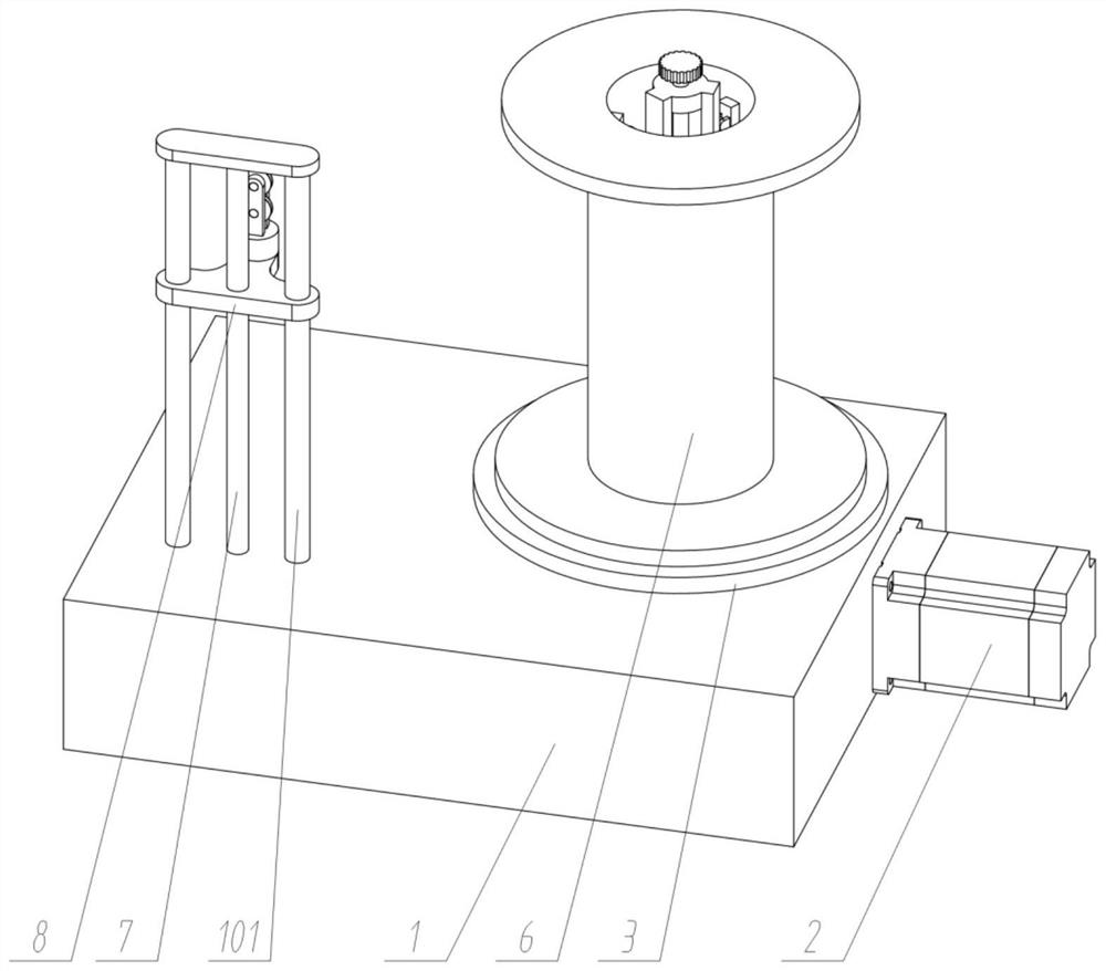
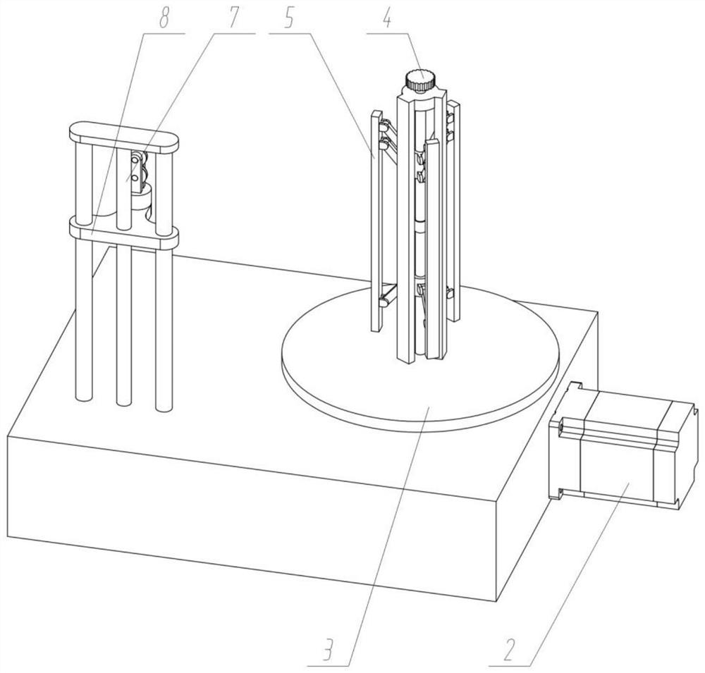
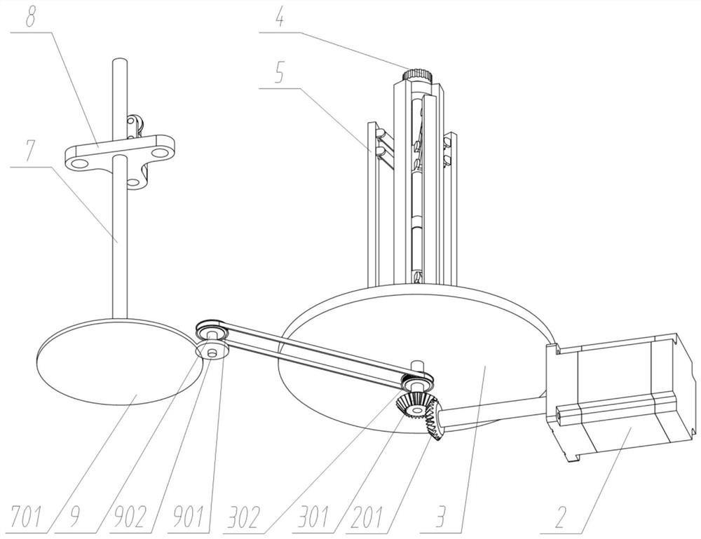
[0027] see Figure 1 to Figure 8 , an embodiment provided by the present invention: a spinning guide collection device used in the textile field, including a mounting base 1; a set of driving parts 2 is fixedly connected to the right side of the mounting base 1; the top right side of the mounting base 1 There is a group of collecting rotating disks 3 connected in rotation; a group of locking knobs 4 is rotatingly connected to the upper part of collecting rotating disks 3; three groups of tensioning blocks 5 are arranged in an outer circumferential array of locking knobs 4; the outer sides of the tensioning blocks 5 are tightened A set of wire hubs 6 is connected; a s...


PUM


Abstract

The invention discloses a yarn guiding and collecting device used in the textile field, and relates to the technical field of textile machinery. The yarn guiding and collecting device solves the problem that an existing yarn guiding device is driven to swing through a driving device to realize the guiding of cotton threads, and when the existing yarn guiding device is in use, the guiding device needs to be additionally controlled, the coordination between the rotation of a collecting device and the swinging of the guiding device is difficult to ensure, and the guiding effect is poor. The yarnguiding and collecting device comprises a mounting base, wherein a group of driving part is fixedly connected to the right side of the mounting base; a group of collecting rotary disk is rotatably connected to the right side of the top of the mounting base; a group of guide driving lead screw is rotatably connected to the left side of the top of the mounting base; and a group of intermediate transmission parts are rotatably connected to the inner side of the bottom of the mounting base. A yarn collecting barrel is adopted by the yarn guiding and collecting device, is stably fixed, and is simple to operate and convenient to use; the automatic adjustment of the height of a guiding part can be realized while yarns are wound, so that the winding height of yarns is adjusted; and the yarn guiding and collecting device realizes the guiding of the yarns, and has a good guiding effect and a good synchronous guiding effect.

Description

technical field [0001] The invention relates to the technical field of textile machinery, in particular to a spinning guide collection device used in the textile field. Background technique [0002] Spinning is an important technological process in the textile processing process. After the spinning is completed, the cotton thread needs to be collected. During the cotton thread collection process, a guiding device is generally required to ensure that the cotton thread is wound neatly. [0003] For example, application number: CN201710741477.9 This patent application belongs to the field of textile machinery, and discloses spinning equipment for cotton thread, including a winding part for cotton thread to pass through and a power part for providing power for the winding part; The line part includes an upper pressing plate and a lower pressing plate that can move relatively; the upper pressing plate and the lower pressing plate are provided with a connecting rod protruding inwa...

Claims


Application Information

Patent Timeline
Patent Type & Authority Applications(China)
IPC IPC(8): D01H1/36D01H13/04
CPCD01H1/36D01H13/04
Inventor 查黎
Owner 查黎
Learn More