Supercharge Your Innovation With Domain-Expert AI Agents!

Well point pipe structure and well point construction method

The technology of well point pipe and well point is applied in the field of well point pipe structure and well point construction, which can solve the problems of easy accumulation of filter material in the well point mouth part of the well point hole and inability to evenly fall into the well point hole, etc. To achieve the effect of improving the uniformity

Active Publication Date: 2021-08-24
福建和盛达建筑工程有限公司
View PDF8 Cites 0 Cited by
  • Summary
  • Abstract
  • Description
  • Claims
  • Application Information

AI Technical Summary

Problems solved by technology

[0004] In view of the above-mentioned related technologies, the inventor believes that there are the following defects: after the well point hole is opened, the pipe body 1 is inserted into the well point hole first, and then the filter material is poured manually. When there is a lot of material, the filter material is easy to accumulate in the well point mouth of the well point hole, and cannot fall into the well point hole evenly

Method used


Image

  • Well point pipe structure and well point construction method
  • Well point pipe structure and well point construction method
  • Well point pipe structure and well point construction method

Examples


Embodiment Construction

[0039] Contraction below Figure 2-7 Further detailed description of the present application.

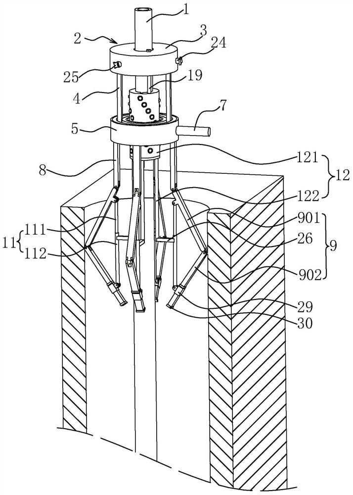
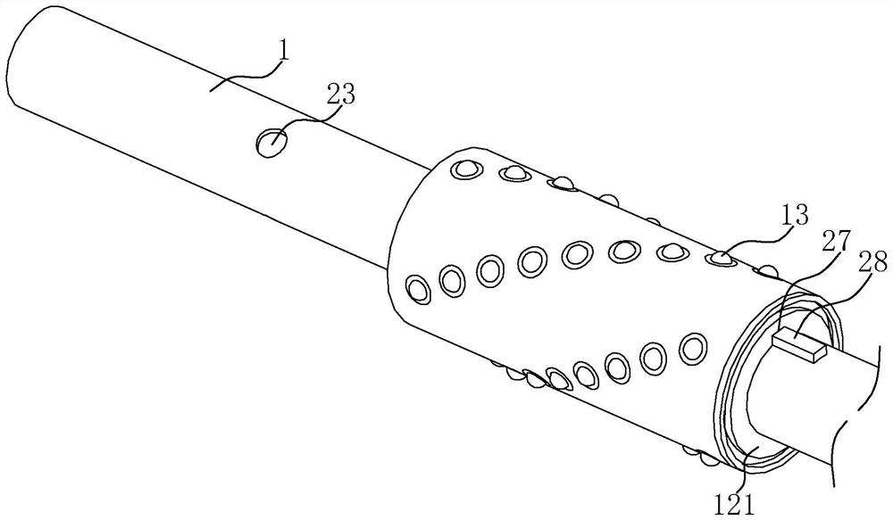
[0040] See figure 2 For a well spot tube disclosed in the present application, including tubing 1 and agitation device 2. The agitation device 2 is disposed in the tubing body 1, first place the tube 1 into the well point hole, and then stir the filled filter material by agitation device 2, so that the filter material can be relatively uniformly removed into the well point hole, lowered filter. It is possible to stacked in the top of the well.

[0041] See figure 2 and Figure 3 The agitation device 2 includes a mount 3, and the mounting sleeve 3 is set in the outer peripheral side of the tube body 1 close to the top portion. The tubular body 1 is uniformly spaced apart from the outer peripheral side, and the mounting sleeve 3 is screwed with the screw 24, and the screw 24 is fixed to the tubular body 1 to secure the knob 25. When using the rotary knob 25, the drive screw 24 is inserted i...


PUM


Abstract

The present application relates to a well point pipe structure and a well point construction method, relates to the technical field of well point dewatering, and improves the problem that the filter material may accumulate at the well point mouth, which includes a pipe body and a stirring device, and the stirring device includes an installation The installation sleeve is fixedly set on the outer peripheral side of the tube, and the bottom of the installation sleeve is symmetrically provided with a connecting column, and the bottom of the connecting column is rotatably connected with a connecting seat, and a connecting hole is opened in the middle of the connecting seat. The body passes through the connecting hole, the outer peripheral side of the connecting seat is provided with a toggle rod for rotating the connecting seat, the bottom of the connecting seat is fixed with connecting rods at even intervals, and the side of the connecting rod far away from the connecting seat is provided with a stirring rod components. The application has the effect of reducing the accumulation of filter material at the well point.

Description

Technical field [0001] The present application relates to the technical field of well spot precipitation, in particular, involving a well spot tube structure and a well point construction method. Background technique [0002] Well point precipitation is a well dotted tube every other spacing area around the foundation pit, and the well point tube is connected to the current collector, and then the water in the foundation of the foundation in the four-week soil layer in the foundation pit is extracted through the vacuum absorbing pump. [0003] Currently, see Figure 1 , A well point tube, including a tubic body 1, and the outer peripheral side of the tube body is wrapped around the bottom of the nylon material. The well spot hole is opened around the foundation pit before use, and then the tube body 1 is inserted into the well point hole, followed by filled with filter material on the tubular body 1 and the well point hole, so that the water in the soil layer is first filtered. Af...

Claims


Application Information

Patent Timeline
Patent Type & Authority Patents(China)
IPC IPC(8): E02D19/10
CPCE02D19/10
Inventor 黄丽娇卓良国黄辉
Owner 福建和盛达建筑工程有限公司
Features
  • R&D
  • Intellectual Property
  • Life Sciences
  • Materials
  • Tech Scout
  • Unparalleled Data Quality
  • Higher Quality Content
  • 60% Fewer Hallucinations
Learn More