Supercharge Your Innovation With Domain-Expert AI Agents!

A large-capacity liquid argon storage safety filling device

A large-capacity, liquid argon technology, applied in the installation device of container structure, fixed-capacity gas storage tank, gas/liquid distribution and storage, etc., can solve the problems of increasing its own weight, difficult movement of the device, and large volume, and achieve weakening Effects of radiation heat transfer, reduction of gas heat transfer, and increase in contact area

Active Publication Date: 2022-04-15
BAOTOU BAOTOU STEEL YINGDA GAS CO LTD
View PDF9 Cites 0 Cited by
  • Summary
  • Abstract
  • Description
  • Claims
  • Application Information

AI Technical Summary

Problems solved by technology

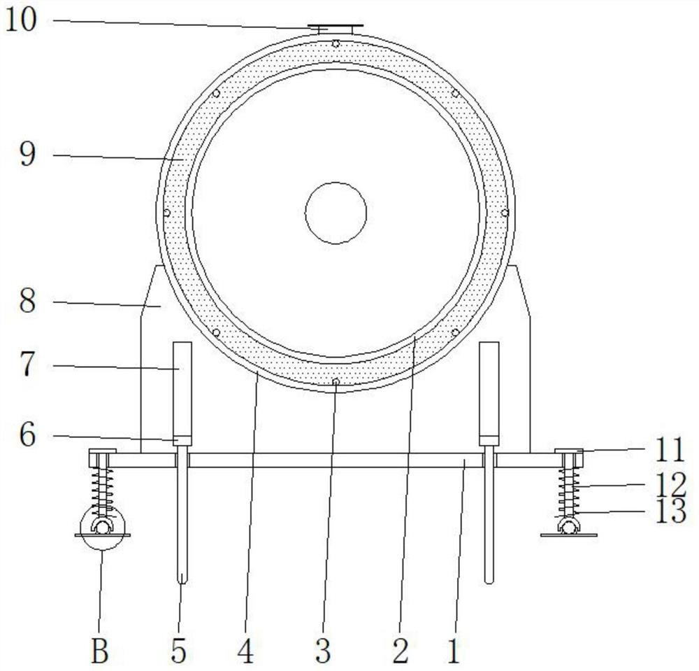
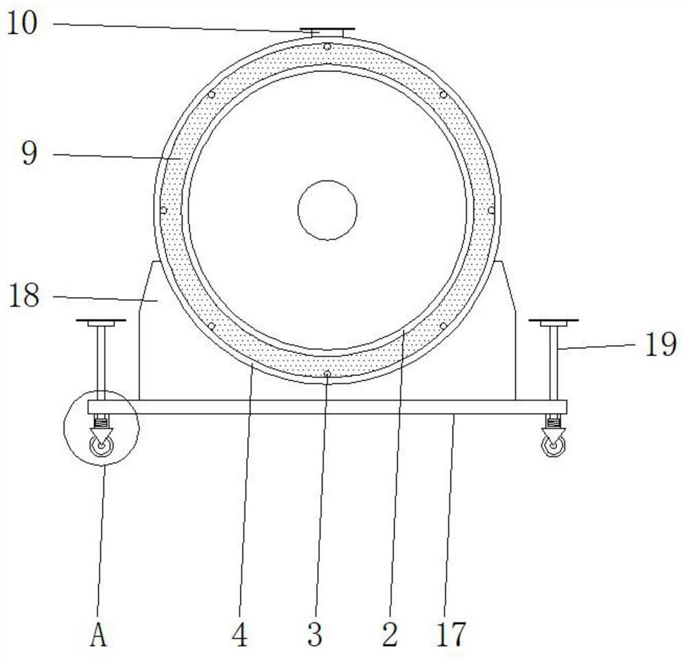
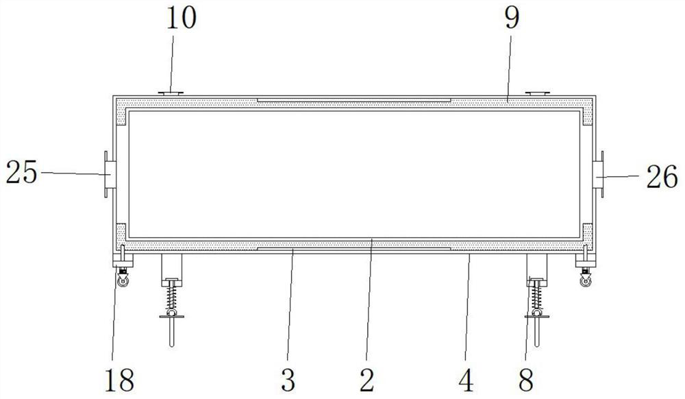
[0007] The purpose of the present invention is to provide a large-capacity liquid argon storage safety filling device, which has a compact structure and is easy to use. While maintaining the stability of the device, it can achieve the purpose of being easy to move by changing its own structure, and adding a vibration reduction structure, reduce the vibration and touch of the device during the hoisting process, achieve the effect of safe transportation, meet the needs of personnel, and solve the problem of the traditional argon storage tank safety storage device due to its large size during use and after loading It further increases its own weight, which makes it difficult to move the device. At the same time, when the device is transferred and hoisted, because it claims to have no shock-absorbing structure, the device will always collide with the contact surface when it is placed, which violates the principle of safe transportation and cannot Meeting the needs of personnel

Method used


Image

  • A large-capacity liquid argon storage safety filling device
  • A large-capacity liquid argon storage safety filling device
  • A large-capacity liquid argon storage safety filling device

Examples


Embodiment Construction

[0024] The following will clearly and completely describe the technical solutions in the embodiments of the present invention with reference to the accompanying drawings in the embodiments of the present invention. Obviously, the described embodiments are only some, not all, embodiments of the present invention. Based on the embodiments of the present invention, all other embodiments obtained by persons of ordinary skill in the art without making creative efforts belong to the protection scope of the present invention.

[0025] In the description of the present invention, it should be noted that the terms "upper", "lower", "inner", "outer", "front end", "rear end", "both ends", "one end", "another end" The orientation or positional relationship indicated by etc. is based on the orientation or positional relationship shown in the drawings, and is only for the convenience of describing the present invention and simplifying the description, rather than indicating or implying that ...


PUM


Abstract

The invention discloses a large-capacity liquid argon storage safety filling device, comprising a support plate, an inner cylinder, an outer casing, a support seat, a mounting seat and a return spring, and both ends of the inner cylinder are welded at the middle positions on both sides of the inner wall of the outer casing A mounting seat is welded on the lower surface of the housing, a mounting plate is welded on the lower surface of the mounting seat, a threaded rod is threaded on the mounting plate, an outer rod is sleeved on the threaded rod, a fixing frame is welded on the outer rod, and the fixing frame is rotated and installed There is a moving wheel, the support seat is symmetrically welded on the shell, and a support plate is welded on the support seat, a sliding rod is inserted on the support plate, a top plate and a ball sleeve are welded on the sliding rod, and a roller ball is installed on the lower surface of the ball sleeve. , A bearing plate is welded on the roller ball, a damping spring is connected to the movable sleeve on the sliding rod, and the damping spring is located between the support plate and the bead sleeve. The present invention achieves the purpose of facilitating movement by changing its own structure, reduces the vibration and touch of the device during the hoisting process, and achieves the effect of safe transportation.

Description

technical field [0001] The invention relates to the technical field of liquid argon storage devices, in particular to a large-capacity liquid argon storage safety filling device. Background technique [0002] In recent years, the cryogenic liquid market has become more and more prosperous. The sales of liquid oxygen, liquid argon, liquid nitrogen, liquid carbon dioxide, and LNG have increased significantly. Therefore, the by-products of oxygen generators are very profitable and have become an important part of the income of non-steel products for iron and steel enterprises. The production, storage, and transportation of cryogenic liquids are inseparable from thermal insulation storage tanks, which are installed and used in large numbers. [0003] Thermal insulation storage tanks are divided into vacuum powder insulation type and atmospheric pressure powder insulation type. Powder insulation uses low thermal conductivity powder, fiber or foam material to reduce heat input. T...

Claims


Application Information

Patent Timeline
Patent Type & Authority Patents(China)
IPC IPC(8): F17C3/08F17C3/04F17C3/02F17C13/00F17C13/04F17C13/08F16F15/067
CPCF17C3/085F17C3/04F17C3/02F17C13/00F17C13/04F17C13/08F16F15/067F17C2201/0119F17C2203/0337F17C2203/0391F17C2203/0308F17C2203/012F17C2203/0629F17C2205/0107F17C2205/0126F17C2205/0161F17C2205/0196
Inventor 白俊辉
Owner BAOTOU BAOTOU STEEL YINGDA GAS CO LTD
Features
  • R&D
  • Intellectual Property
  • Life Sciences
  • Materials
  • Tech Scout
  • Unparalleled Data Quality
  • Higher Quality Content
  • 60% Fewer Hallucinations
Learn More