Chemical tail gas dedusting spraying device

A technology of spraying device and chemical tail gas, which is applied in the direction of transportation and packaging, chemical instruments and methods, and filtration of dispersed particles, which can solve the problems of low flue gas treatment efficiency and inability to remove dust, and achieve high-efficiency absorption and ensure network The effect of unimpeded board and efficient dust filtration effect

Inactive Publication Date: 2020-11-17
吴菊芬
View PDF4 Cites 5 Cited by
  • Summary
  • Abstract
  • Description
  • Claims
  • Application Information

AI Technical Summary

Problems solved by technology

Although the device can be used to absorb and treat tail gas, it cannot fully remove the dust in the flue gas during the treatment process, resulting in low flue gas treatment efficiency. Therefore, a chemical tail gas dust removal spray is now provided device to solve the above technical problems

Method used


Image

  • Chemical tail gas dedusting spraying device
  • Chemical tail gas dedusting spraying device
  • Chemical tail gas dedusting spraying device

Examples


Embodiment 1

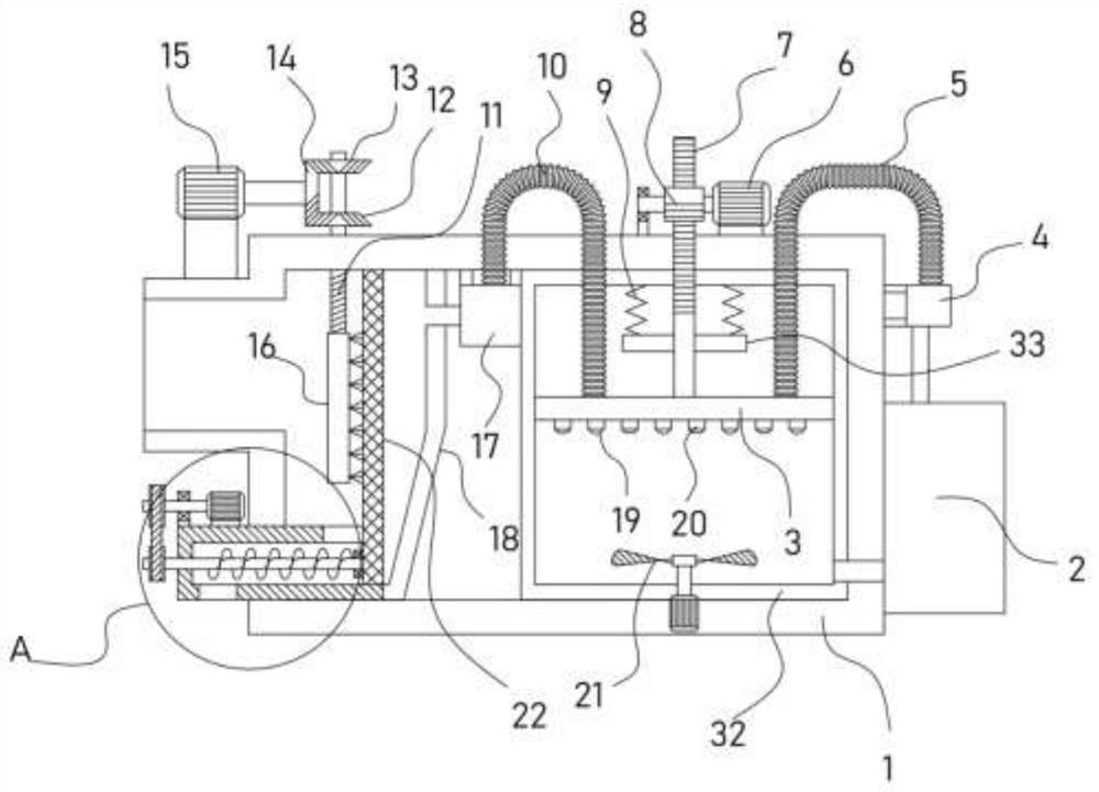
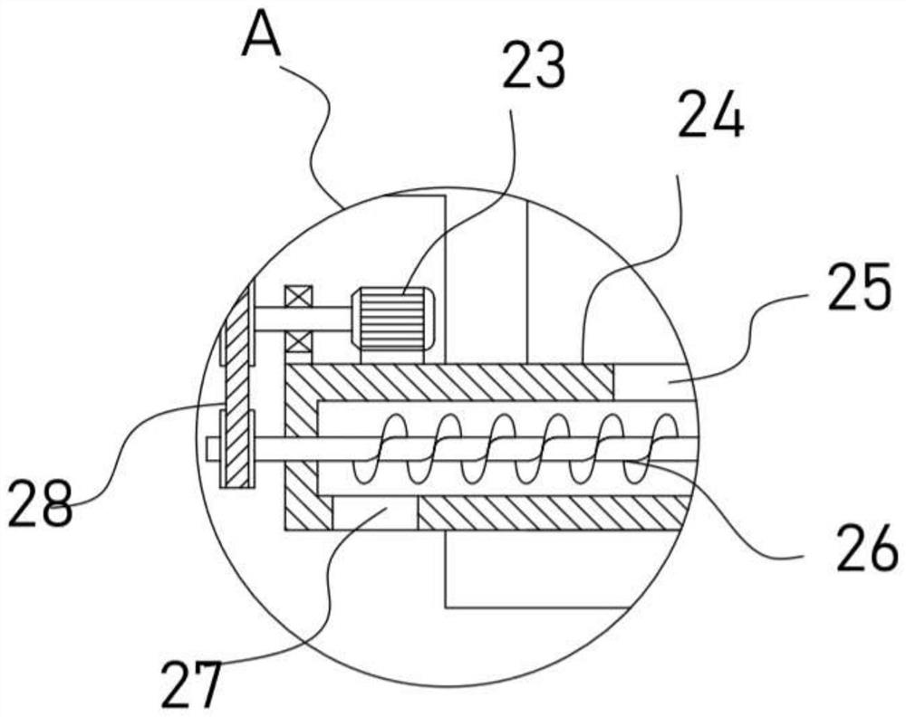
[0023] see Figure 1-4 , a chemical tail gas dedusting spraying device, comprising a support frame 1, a dust removal box 18 and an absorption box 32 are arranged in the support frame 1, a dust filter screen 22 is vertically fixed in the dust removal box 18, and a dust filter screen 22 is fixed on the top of the support frame 1 The motor II15 is driven and connected with a cleaning mechanism for cleaning the dust filter screen 22. The dust removal box 18 is provided with a conveying mechanism for conveying the dust. The top of the support frame 1 is fixed with a motor I6 and a motor I6. The upper drive is connected with a vertical reciprocating mechanism, and the vertical reciprocating mechanism is driven and connected with an air jet disc 3 communicating with the inside of the dust removal box 18. The side wall of the support frame 1 is fixed with a liquid medicine tank 2, which is connected to a The spray mechanism in the absorption box 32.

[0024] The exhaust gas of chemic...

Embodiment 2

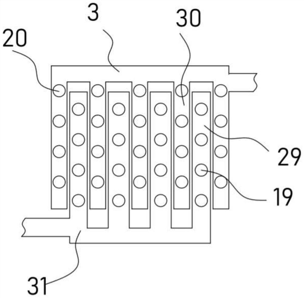
[0030] On the basis of Embodiment 1, in addition, the delivery pump 17 communicating with the dust removal box 18 is fixed on the support frame 1, and the bellows II10 communicating with the air injection disc 3 is installed at the outlet end of the delivery pump 17, and the equal intervals on the delivery air injection disc 3 Several extension pipes II30 are installed, and several smoke nozzles 20 are evenly installed on the extension pipes II30.

[0031] The conveying pump 17 pumps the exhaust gas in the dust removal box 18, and the exhaust gas enters the interior of the gas injection plate 3 along the bellows II10, and finally sprays out from the smoke nozzle 20. The spray mechanism includes a lift pump 4 connected to the liquid medicine tank 2 , a bellows I5 is installed on the lifting pump 4, a liquid medicine spray plate 31 is installed on the bellows I5, and several extension pipes I29 interlaced with the extension pipe II30 are installed on the liquid medicine spray pla...


PUM


Abstract

The invention discloses a chemical tail gas dedusting spraying device, which relates to the technical field of chemical tail gas treatment. The device comprises a support frame, wherein a dedusting box and an absorption box are arranged in the support frame; a dust filtration screen plate is vertically fixed in the dedusting box a motor I is in driving connection with a vertical reciprocating mechanism; the vertical reciprocating mechanism is in driving connection with an air injection disc communicated with the interior of the dedusting box; a spraying mechanism located in the absorption boxis connected to a liquid reagent box. Dust in flue gas is filtered through the arranged dust filtration screen plate, an arranged cleaning mechanism is driven by a motor II to drive a brush plate to vertically reciprocate, the brush plate is promoted to fully clean dust attached to the dustfiltration screen plate to ensure that the screen plate of the dust filtering screen plate is smooth, and theefficient dust filtering effect of the dust filtering screen plate on flue gas is effectively guaranteed. Flue gas can be dispersed and sprayed out through an arranged flue gas spray head, meanwhile,a liquid reagent sprayed out of a liquid reagent spray head makes full contact with the flue gas, and the efficient absorption effect is achieved.

Description

technical field [0001] The invention relates to the technical field of chemical tail gas treatment, in particular to a chemical tail gas dedusting and spraying device. Background technique [0002] Chemical industry is the abbreviation of "chemical technology", "chemical industry", "chemical engineering" and so on. Any technology that uses chemical methods to change the composition and structure of substances or to synthesize new substances belongs to chemical production technology, that is, chemical technology, and the resulting products are called chemicals or chemical products. At first, it was a manual workshop that produced such products, and later evolved into a factory, and gradually formed a specific production industry, that is, the chemical industry. The tail gas in the chemical production process needs to be absorbed and treated by a treatment device. [0003] The patent application publication No. CN109731427 A discloses a chemical equipment tail gas treatment d...

Claims


Application Information

Patent Timeline
Patent Type & Authority Applications(China)
IPC IPC(8): B01D46/10B01D46/00B01D53/18
CPCB01D46/10B01D53/18B01D46/681
Inventor 吴菊芬
Owner 吴菊芬
Why Eureka
Try Eureka