Check patentability & draft patents in minutes with Patsnap Eureka AI!

Building steel pipe derusting device

A technology for steel pipes and construction, applied in the field of construction steel pipe rust removal devices, can solve problems such as wasting energy, and achieve the effects of reducing wear, increasing applicability, and increasing practicability

Inactive Publication Date: 2020-11-17
张慧
View PDF0 Cites 2 Cited by
  • Summary
  • Abstract
  • Description
  • Claims
  • Application Information

AI Technical Summary

Problems solved by technology

[0003] The existing steel pipe derusting device uses multiple power sources to rotate and derust the steel pipe respectively, which wastes a lot of energy. Therefore, there is a need for a construction steel pipe derusting device that uses a single power source to rotate and derust the steel pipe

Method used


Image

  • Building steel pipe derusting device
  • Building steel pipe derusting device
  • Building steel pipe derusting device

Examples


Embodiment 1

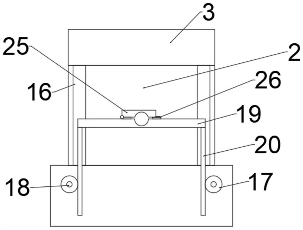
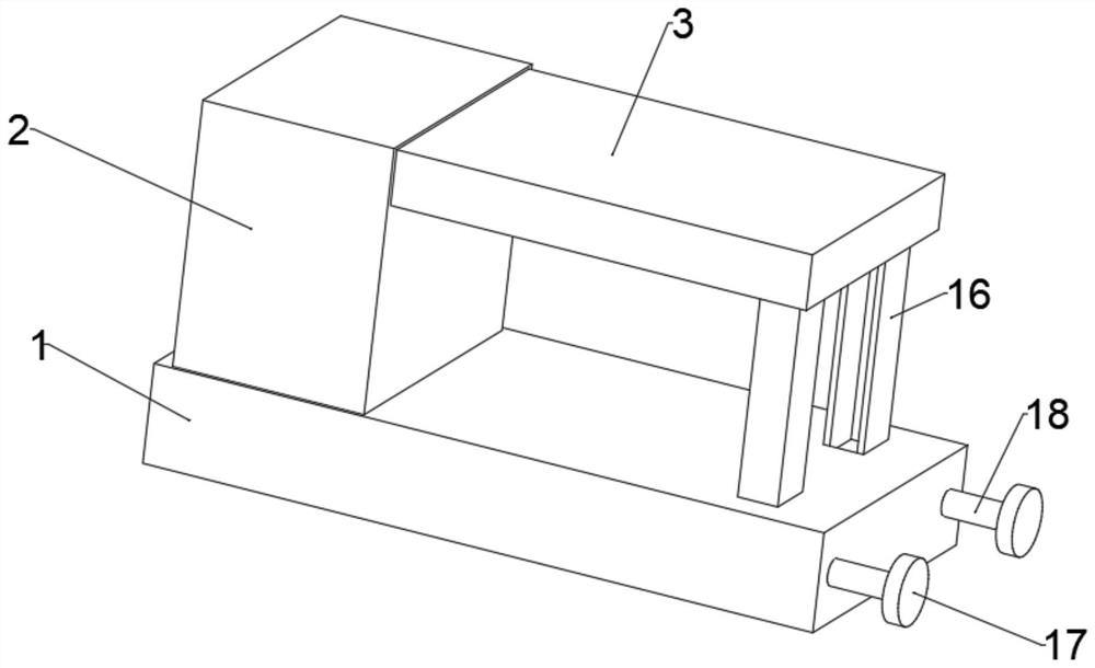
[0033] refer to Figure 1 ~ Figure 3, a construction steel pipe derusting device, comprising a bottom plate 1, a support box 2 is connected with bolts on the upper left side of the bottom plate 1, a top box 3 is connected with bolts on the upper right side of the support box 2, and the top box 3 is far away from the bottom of one end of the support box 2 There are several support columns 16 connected by bolts, and a placement plate 19 is arranged between the two support columns 16. One end of the support columns 16 away from the top box 3 is fixedly connected to the bottom plate 1, and the bottom left side of the support box 2 is bolted to a first The fixed plate 4, the upper bolt of the first fixed plate 4 is connected with the rotating motor 5, the output end shaft of the rotating motor 5 is connected with the rotating shaft 6, the upper axis of the rotating shaft 6 is fixed with the first driving gear 7, and the rotating shaft 6 runs through the support box 2, the end of th...

Embodiment 2

[0041] refer to Figure 4 ~ Figure 5 , a construction steel pipe derusting device. Compared with Embodiment 1, this embodiment is provided with a clamping mechanism in the clamping block 15. The clamping mechanism includes an adjusting shaft 32, a driving helical gear 33, a driven helical gear 34, a second Two power transmission shafts 35, the second driving gear 36, the second driven gear 27, the third screw mandrel 28, the third bearing seat 37, the fifth fixed plate 38 and the clamping plate 39, the surface of the clamping block 15 is rotatably connected with Several adjusting shafts 32, the lower shaft of the adjusting shaft 32 is fixed with a driving helical gear 33, the right side of the driving helical gear 33 is meshed with a driven helical gear 34, and the central axis of the driven helical gear 34 is fixed with a second transmission shaft 35 , the middle part of the second transmission shaft 35 is provided with a threaded structure, the second transmission shaft 35 i...


PUM


Abstract

The invention discloses a building steel pipe derusting device which comprises a bottom plate, wherein a supporting box is arranged on the left side of the upper portion of the bottom plate, a top boxis arranged on the upper portion of the right side of the supporting box, a plurality of supporting columns are arranged below the end, away from the supporting box, of the top box, a placing plate is arranged between the two supporting columns, and the ends, away from the top box, of the supporting columns are fixedly connected with the bottom plate. A first fixing plate is arranged on the leftside of the lower portion in the supporting box, a rotating motor is arranged above the first fixing plate, a rotating shaft is arranged at the output end of the rotating motor, and a first driving gear is arranged on the rotating shaft. When the device starts to operate, a steel pipe is placed on the placing plate, the steel pipe is clamped through clamping blocks, a first driven gear drives a first lead screw to rotate, and a hydraulic pipe drives a derusting head to do left-right reciprocating motion, so that the derusting head conducts sufficient derusting on the steel pipe; and the devicerotates and removes rust the steel pipe by adopting a single power source, so that the energy is saved, and the device is suitable for large-scale popularization.

Description

technical field [0001] The invention relates to the technical field of construction steel pipes, in particular to a derusting device for construction steel pipes. Background technique [0002] Steel pipes for construction can be divided into seamless steel pipes and seamed steel pipes according to the seamlessness of seams. Seamed steel pipes are divided into spiral steel pipes and straight seam steel pipes according to the different welds. The two are widely used in construction piling, structure, steel structure, load-bearing, drainage and other aspects. The materials mainly include carbon steel, stainless steel, and alloy steel, among which carbon steel is the most commonly used. Steel pipes for construction are used in building construction, and are generally directly exposed to the external environment. The surface of the steel pipe is prone to rust, so it needs to be derusted before use. [0003] Existing steel pipe derusting devices use multiple power sources to rot...

Claims


Application Information

Patent Timeline
Patent Type & Authority Applications(China)
IPC IPC(8): B24B27/033B24B5/04B24B47/12B24B47/16B24B55/06B24B55/00B24B41/06
CPCB24B5/04B24B27/033B24B41/062B24B47/12B24B47/16B24B55/00B24B55/06
Inventor 张慧
Owner 张慧
Features
  • R&D
  • Intellectual Property
  • Life Sciences
  • Materials
  • Tech Scout
  • Unparalleled Data Quality
  • Higher Quality Content
  • 60% Fewer Hallucinations
Learn More