A graphene plate shearing device with trimming and unloading function and its application method
A shearing equipment and graphene technology, applied in the field of graphene plate shearing equipment with trimming and unloading functions, can solve problems such as increasing labor intensity, reducing work efficiency, and uneven shearing, achieving reduction The effect of artificial labor intensity, improvement of equipment applicability, and reduction of use cost
- Summary
- Abstract
- Description
- Claims
- Application Information
AI Technical Summary
Problems solved by technology
Method used
Image
Examples
Embodiment 1
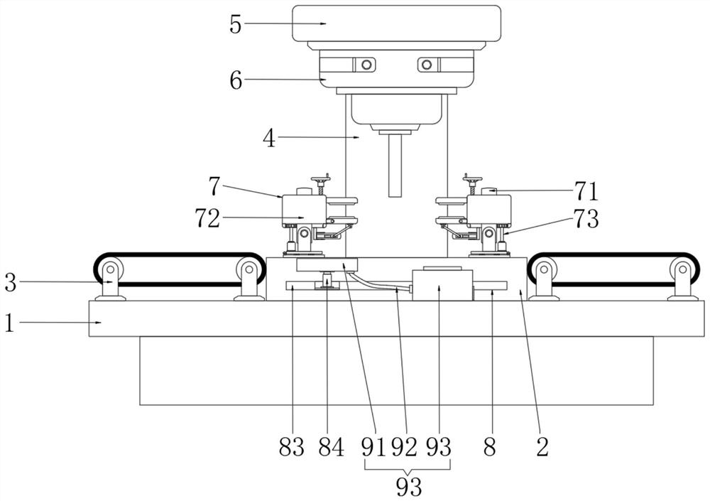
[0024] Embodiment 1: a kind of graphene plate shearing equipment with trimming discharge function, please refer to 1, a kind of graphene plate shearing equipment with trimming discharge function, including workbench 1, discharge conveyor belt The device 3, the shearing device 6, and the unloading conveyor belt device 3 are widely used in this field, and specifically include two groups of brackets, and the tops of the two groups of brackets are provided with roller bodies through rotating shafts, and the two groups of roller bodies are connected by transmission belts, wherein the left The rear end of the side shaft runs through the rear side of the left bracket and is connected with the drive motor. The drive motor is fixed on the outer wall of the rear side of the left bracket. The left unloading conveyor belt device 3 drives the cut and trimmed graphene plate to the left for unloading. , the right side unloading conveyor belt device 3 drives the graphene plate that has sheared...
Embodiment 2
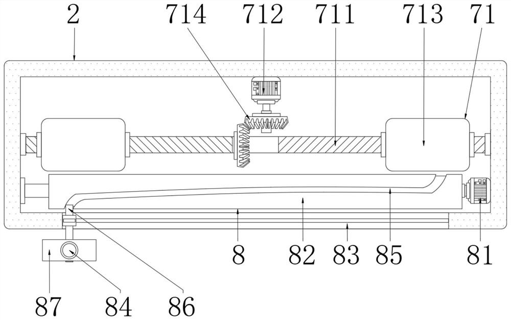
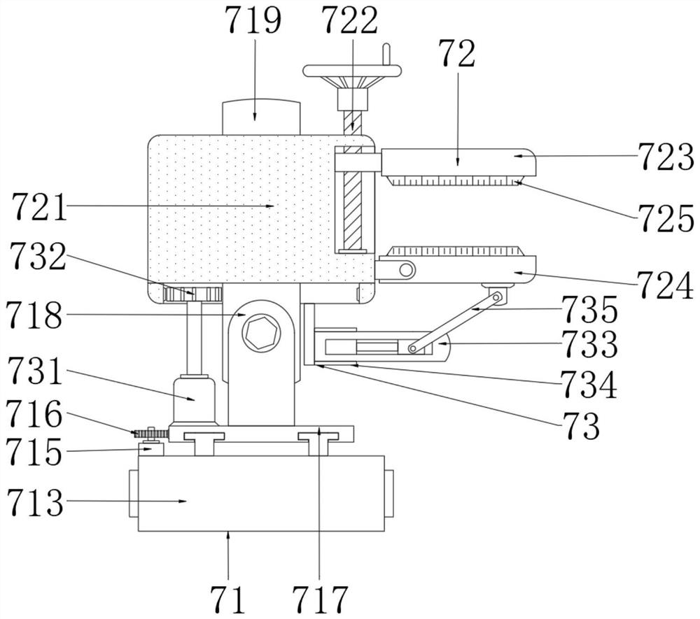
[0026] Embodiment 2: This embodiment is different from the above embodiment, please refer to figure 2 with image 3 , the receiving mechanism 71 includes a two-way lead screw 711, which is used to drive two groups of assembly blocks 713 to approach or move away from each other, and adjust the distance according to the length of the graphene plate. The two-way lead screw 711 is arranged in the receiving box 2 for lateral movement In the middle of the cavity, the left and right ends of the two-way lead screw 711 are respectively movably connected to the left and right inner walls of the receiving box 2 through bearings, and the left and right sides of the outer wall of the two-way lead screw 711 are threaded with assembly blocks 713, and the two sets of assembly blocks 713 are all located in the receiving box 2. And the tops of two groups of assembly blocks 713 all run through the top of the receiving box 2, and the left and right sides of the top of the receiving box 2 are hor...
Embodiment 3
[0027] Embodiment 3: The difference between this embodiment and the above-mentioned embodiment is that please refer to image 3 , the fixing mechanism 72 includes a sleeve 721 which is movably sleeved on the top of the outer wall of the receiving column 719 through bearings, which facilitates the rotation of the sleeve 721 and prevents the sleeve 721 from moving up and down. The bottom of the outer wall of the sleeve 721 near the center of the receiving box 2 is hinged Lower pressing plate 724, lower pressing plate 724 is used for cooperating with upper pressing plate 723, sleeve 721 is provided with upper pressing plate 723 corresponding to lower pressing plate 724 near the side outer wall top of receiving box 2 center, upper pressing plate 723 is used for the The graphene plate is compressed on the lower pressing plate 724, and the upper pressing plate 723 is fixedly provided with a T-shaped slider away from the center of the receiving box 2, and the sleeve 721 is vertically ...
PUM
 Abstract
Description
Claims
Application Information
 - R&D
- Intellectual Property
- Life Sciences
- Materials
- Tech Scout
- Unparalleled Data Quality
- Higher Quality Content
- 60% Fewer Hallucinations
Browse by: Latest US Patents, China's latest patents, Technical Efficacy Thesaurus, Application Domain, Technology Topic, Popular Technical Reports.
© 2025 PatSnap. All rights reserved.Legal|Privacy policy|Modern Slavery Act Transparency Statement|Sitemap|About US| Contact US: help@patsnap.com


