Hydraulic pier protection device

A protection device and bridge pier technology, applied in bridges, bridge parts, bridge construction, etc., can solve problems such as excessive kinetic energy and bridge pier damage

Pending Publication Date: 2020-11-17
温州砼程维禹科技有限公司
View PDF10 Cites 4 Cited by
  • Summary
  • Abstract
  • Description
  • Claims
  • Application Information

AI Technical Summary

Problems solved by technology

[0004] The present invention intends to provide a hydraulic pier protection device to solve the problem...

Method used


Image

  • Hydraulic pier protection device
  • Hydraulic pier protection device
  • Hydraulic pier protection device

Examples


Embodiment

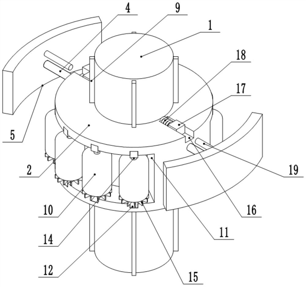
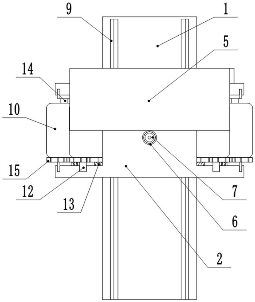
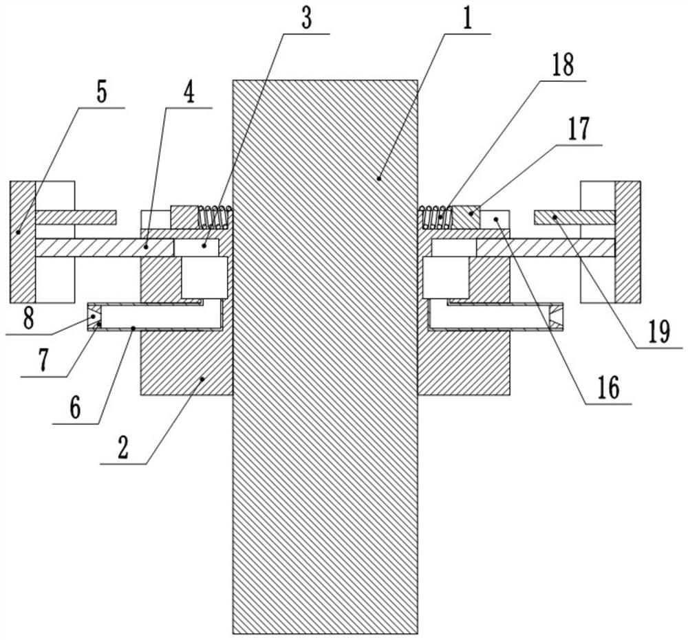
[0022] Such as figure 1 , figure 2 and image 3 Shown: a hydraulic pier protection device, including a pier 1 whose lower end is submerged in the water, a ring-shaped load-bearing platform 2 is set on the pier 1, and several guide columns 9 are fixed around the pier 1, and the guide columns 9 are vertically arranged The inner wall of the load-bearing platform 2 is provided with a number of grooves for accommodating the guide columns 9, and the load-bearing platform 2 is slidably connected to the pier 1 through the guide columns 9; a number of floating rubber cylinders 10 are also fixed on the side walls of the load-bearing platform 2, and the floating rubber cylinders 10 are in the form of Distributed in a circular array, arc-shaped grooves 11 are opened on both side walls of the load-bearing platform 2, and a number of axial chutes are opened at the upper and lower ends of the arc-shaped groove 11, and the chutes are distributed in a circumferential array. Slidingly connec...

specific Embodiment approach

[0023] The floating rubber tube 10 drives the load-bearing platform 2 to float on the water surface as a whole, and cooperates with the cooperation between the guide column 9 and the groove to make the device float with the rise and fall of the water level, and keep the device floating on the water surface to protect the pier 1 at any time.

[0024] When the ship hits the protective plate 5, the protective plate 5 is pushed to slide, and the protective plate 5 drives the pressure rod 4 to slide in the first transverse groove 3, thereby pressurizing the water in the hydraulic chamber and the first transverse groove 3, At this time, the water in the hydraulic chamber and the first horizontal groove 3 has the effect of hydraulic buffering, which consumes energy for the first time on the ship; and the pressurized water is sprayed out through the outlet pipe 6, and the The diameter of the water spray hole 8 is smaller than the diameter of the water outlet pipe 6, and the water is fu...


PUM


Abstract

The invention relates to the field of bridge construction, and particularly discloses a hydraulic bridge pier protection device. The hydraulic bridge pier protection device comprises a bridge pier with the lower end immersed in the water surface, the bridge pier is sleeved with an annular bearing table, symmetrical first transverse grooves are formed in the two side walls of the bearing table, thefirst transverse grooves are horizontally formed, pressurizing rods are slidably connected into the first transverse grooves, protective plates are fixed at the end parts of the pressurizing rods, hydraulic cavities are formed under the first transverse grooves correspondingly and communicate with the corresponding first transverse grooves correspondingly, second transverse grooves parallel to the first transverse grooves are formed in the two side walls of the bearing table correspondingly and located under the first transverse grooves, L-shaped water outlet pipes are arranged in the secondtransverse grooves, the vertical ends of the water outlet pipes communicate with the hydraulic cavities, the water outlet pipes and the first transverse grooves are immersed under the water surface, circular pressurizing plates are fixed to the ends of the water outlet pipes, and water spraying holes are formed in the circle centers of the pressurizing plates. The hydraulic bridge pier protectiondevice solves the problem that when a ship impacts a pier, kinetic energy of the ship is too large, and consequently the pier is greatly damaged.

Description

technical field [0001] The invention relates to the technical field of bridge construction, and specifically discloses a hydraulic bridge pier protection device. Background technique [0002] With the rapid development of the transportation industry, the number of large bridges spanning navigable rivers, port areas and straits recently built in my country has gradually increased, and the number of ships on the waterway has also continued to increase and the ship types tend to be larger, making the bridge and the passage of ships more and more difficult. The contradiction between them is becoming more and more prominent, so the accidents of ships colliding with bridge piers are also increasing. The structural damage caused by the impact of the ship on the bridge reduces the bearing capacity and durability of the bridge within the design life to a certain extent, and even leads to the collapse of the entire structure. [0003] In the prior art, the protective structure of the ...

Claims


Application Information

Patent Timeline
IPC IPC(8): E02B3/26E01D19/02
CPCE02B3/26E01D19/02Y02A30/30
Inventor 李华强
Owner 温州砼程维禹科技有限公司
Why Eureka
Try Eureka