Crank connecting rod type electromechanical inerter device

A crank-link mechanism and crank-link technology, which is applied in electromechanical devices, inertial effect dampers, electrical components, etc., can solve the problem that the working performance of the inerter cannot be guaranteed, the gear teeth or the screw are broken, and the insulation of the inerter is affected. Vibration performance and other issues, to achieve the effect of rich variety, stable performance and simple mode of action

Active Publication Date: 2020-11-17
JIANGSU UNIV
View PDF13 Cites 1 Cited by
  • Summary
  • Abstract
  • Description
  • Claims
  • Application Information

AI Technical Summary

Problems solved by technology

Some of the existing structures are only at the theoretical stage, and only a few mature structures are easy to manufacture, which verifies the effectiveness of the structure. However, in the relevant patents, there is very little determination of the physical material of the inerter, and the actual inerter performance cannot be guaranteed
[0004] In addition, the existing inerters cannot guarantee stable operation under the impact of large loads. Like mechanical inerters, such as rack and pinion inerters and ball screw inerters, once a large load is impacted, the gear teeth or screw It is easy to break or increase the influence of nonlinear factors, thus affecting the vibration isolation performance of the inerter; while the hydraulic inerter, such as the hydraulic piston inerter and the fluid inerter, is faced with the problem of sealing sexual issues

Method used


Image

  • Crank connecting rod type electromechanical inerter device
  • Crank connecting rod type electromechanical inerter device
  • Crank connecting rod type electromechanical inerter device

Examples


Embodiment Construction

[0040] The present invention will be further described below in conjunction with the accompanying drawings and specific embodiments, but the protection scope of the present invention is not limited thereto.

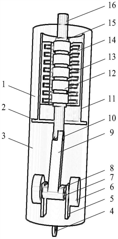
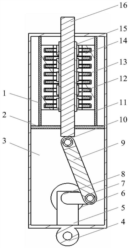
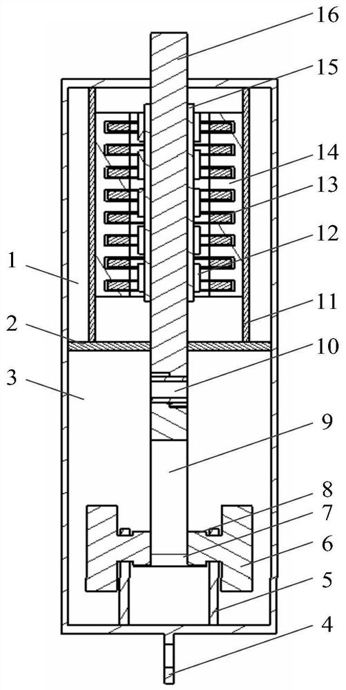
[0041] Such as Figure 1-3 As shown, the present invention relates to a crank-link type electromechanical inerter device, comprising: a linear motor working chamber 1, an intermediate partition plate 2, an inerter working chamber 3, a cylinder 4, a crank shaft seat 5, a flywheel 6, and a crank pin 7. Crank 8, connecting rod 9, connecting rod pin 10, motor barrel 11, magnetic pole 12, winding coil 13, stator core 14, mover yoke 15, motor shaft 16.

[0042] Wherein, the cylinder barrel 4 is divided into a linear motor working chamber 1 and an inerter working chamber 3 by an intermediate partition 2 . A cylindrical linear motor is installed in the working chamber 1 of the linear motor, which is composed of a motor barrel 11 , magnetic poles 12 , winding coils 13 , stator co...


PUM


Abstract

The invention discloses a crank connecting rod type electromechanical inerter device which is formed by coupling a crank connecting rod type inerter and a cylindrical linear motor. The crank connecting rod type inerter utilizes a crank connecting rod mechanism to convert the reciprocating linear motion of a driving straight rod into the reciprocating rotary motion of a flywheel, so that an inertiaeffect is generated, the inerter is formed, and the structure variety of the inerter is enriched. Besides, due to the structural characteristics of the crank connecting rod mechanism, the crank connecting rod type inerter can stably operate under large-load impact, and the application range of the inerter is widened. Materials of main components of the crank connecting rod type inerter are selected, and the stability of the working performance of the crank connecting rod type inerter is guaranteed. Meanwhile, the cylindrical linear motor is connected with an outer-end circuit, so that three working modes of energy feedback, passive control and active control of the crank connecting rod type electromechanical inerter are realized.

Description

technical field [0001] The invention relates to the technical field of engineering vibration isolation, in particular to a novel crank-link type electromechanical inerter device. Background technique [0002] In 2002, Professor Smith of the University of Cambridge proposed the concept of an inerter, which broke through the limitation of a single-end "grounding" of a mass element and demonstrated superior vibration isolation performance. Since then, the inerter has received extensive attention in the field of engineering vibration isolation. In the past ten years, the inerter has been greatly developed, and a number of effective inerter models have emerged. [0003] Although the inerter has experienced more than ten years of development, its realization is still limited to several existing structures, and there are few types of structures. Some of the existing structures are only at the theoretical stage, and only a few mature structures are easy to manufacture in practice, ...

Claims


Application Information

Patent Timeline
IPC IPC(8): F16F7/10H02K7/065H02K7/075H02K7/10
CPCF16F7/10H02K7/065H02K7/075H02K7/10
Inventor 杨晓峰何涛沈钰杰刘雁玲符昊宋航刘昌宁杨艺
Owner JIANGSU UNIV
Why Eureka
Try Eureka