
Unmanned aerial vehicle contraction frame for carrying panoramic camera

A technology of panoramic camera and machine retractable frame, which is applied in the direction of machine platform/bracket, aircraft parts, supporting machines, etc. It can solve the problems of inconvenient take-off and landing of drones, hidden dangers of panoramic camera safety, etc., and achieve the effect of convenient take-off and landing operations

Active Publication Date: 2020-11-17
酷景传媒(上海)有限公司
View PDF7 Cites 4 Cited by
  • Summary
  • Abstract
  • Description
  • Claims
  • Application Information

AI Technical Summary

Problems solved by technology

[0003] At present, installing a panoramic camera on a drone can maximize the shooting range, and the pictures taken are more visual and artistic. Installing a panoramic camera on a drone usually uses a vertical pole to install the lens at the end of the pole , to prevent the drone's flying picture from falling into the shooting range during the camera shooting process. Since the long pole cannot be stored when the drone lands, the panoramic camera will land first, which brings certain safety hazards to the panoramic camera, which is not convenient Takeoff and Landing of Drones

Method used


Image

  • Unmanned aerial vehicle contraction frame for carrying panoramic camera
  • Unmanned aerial vehicle contraction frame for carrying panoramic camera
  • Unmanned aerial vehicle contraction frame for carrying panoramic camera

Examples


Embodiment Construction

[0029] The following will clearly and completely describe the technical solutions in the embodiments of the present invention with reference to the accompanying drawings in the embodiments of the present invention. Obviously, the described embodiments are only some, not all, embodiments of the present invention. Based on the embodiments of the present invention, all other embodiments obtained by persons of ordinary skill in the art without making creative efforts belong to the protection scope of the present invention.

[0030] In describing the present invention, it should be understood that the terms "center", "longitudinal", "transverse", "length", "width", "thickness", "upper", "lower", "front", " Orientation indicated by rear, left, right, vertical, horizontal, top, bottom, inside, outside, clockwise, counterclockwise, etc. The positional relationship is based on the orientation or positional relationship shown in the drawings, and is only for the convenience of describin...


PUM


Abstract

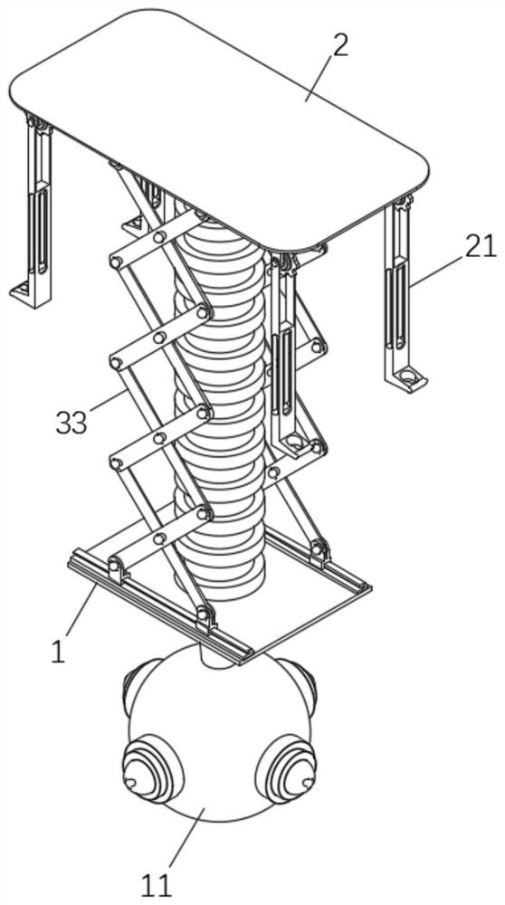
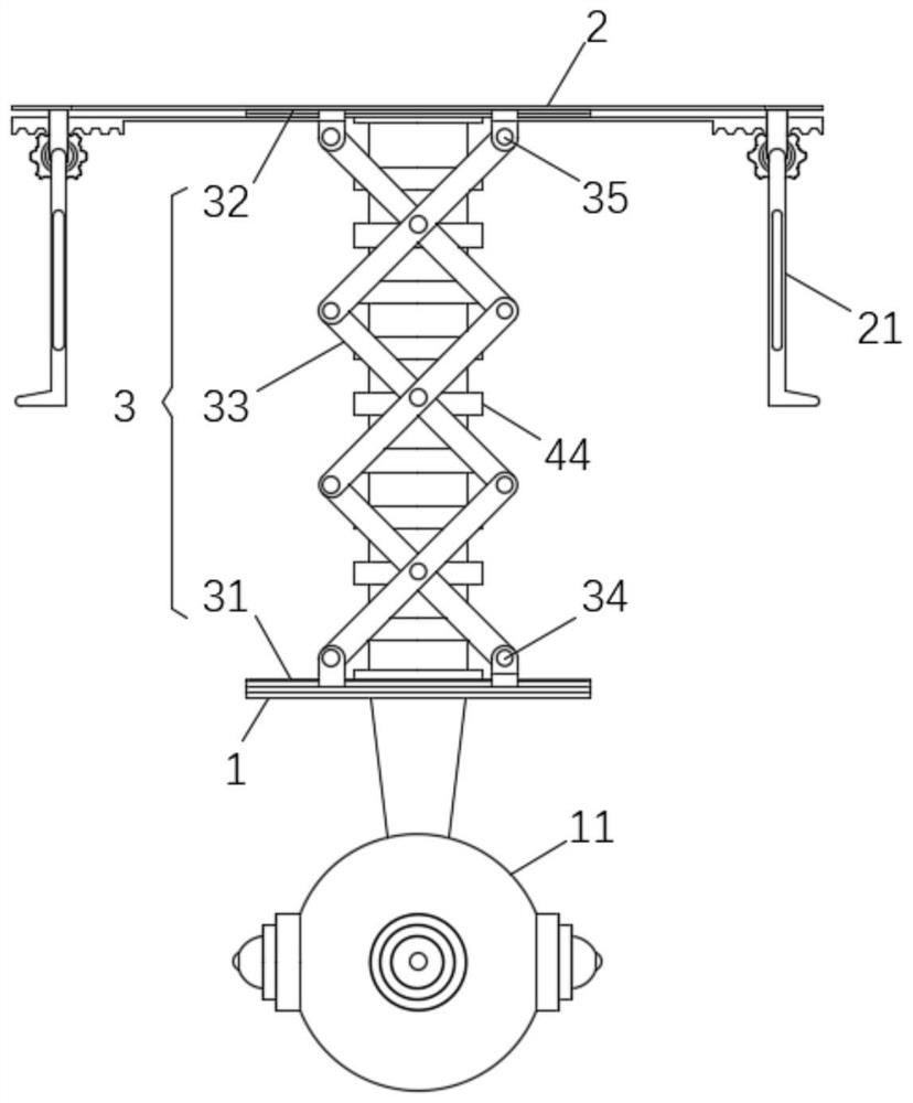
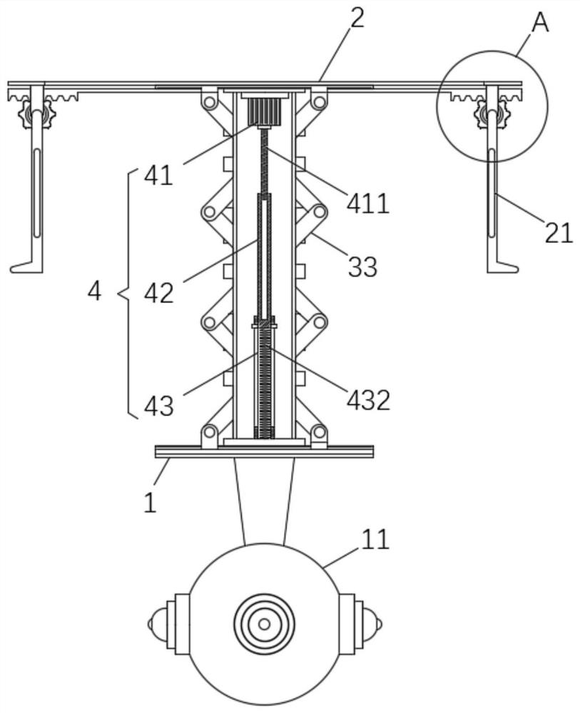
The invention relates to the technical field of unmanned aerial vehicle panoramic camera shooting, in particular to an unmanned aerial vehicle contraction frame for carrying a panoramic camera. The unmanned aerial vehicle contraction frame comprises a bottom plate and a top plate, wherein the panoramic camera is installed on the lower surface of the bottom plate, the top plate is installed on thebottom surface of an unmanned aerial vehicle, supporting legs are arranged at four corners of the lower surface of the top plate, a telescopic mechanism and a driving mechanism are arranged between the bottom plate and the top plate, and the driving mechanism is used for driving the telescopic mechanism to stretch out and draw back. According to the unmanned aerial vehicle contraction frame for carrying the panoramic camera, when the driving mechanism is used for driving the telescopic mechanism to extend, an image of the unmanned aerial vehicle cannot fall into the view finding range of the panoramic camera, meanwhile, when the driving mechanism drives the telescopic mechanism to contract, the ground clearance of the panoramic camera is larger than that of the supporting legs, so that thepanoramic camera is prevented from being accidentally damaged when the unmanned aerial vehicle takes off and lands, and taking-off and landing operation of the unmanned aerial vehicle is facilitated.

Description

technical field [0001] The invention relates to the technical field of unmanned aerial vehicle panoramic photography, in particular to an unmanned aerial vehicle retractable frame for carrying a panoramic camera. Background technique [0002] Unmanned aircraft, referred to as "UAV", is an unmanned aircraft that is controlled by radio remote control equipment and its own program control device, or is completely or intermittently operated autonomously by an on-board computer. UAVs are often better suited for missions in special environments than manned aircraft. [0003] At present, installing a panoramic camera on a drone can maximize the shooting range, and the pictures taken are more visual and artistic. Installing a panoramic camera on a drone usually uses a vertical pole to install the lens at the end of the pole , to prevent the drone's flying picture from falling into the shooting range during the camera shooting process. Since the long pole cannot be stored when the d...

Claims


Application Information

Patent Timeline
Patent Type & Authority Applications(China)
IPC IPC(8): F16M13/02F16M11/04F16M11/18B64D47/00
CPCF16M13/027F16M11/046F16M11/18B64D47/00
Inventor 王一霖王伟
Owner 酷景传媒(上海)有限公司
Learn More