Anti-drop plug and socket based on thermal expansion principle

A kind of anti-detachment and thermal expansion technology, which can be applied to the parts of the connecting device, the two-part connecting device, electrical components, etc., and can solve the problem of the plug easily falling off

Pending Publication Date: 2020-11-17
付相勇
View PDF5 Cites 1 Cited by
  • Summary
  • Abstract
  • Description
  • Claims
  • Application Information

AI Technical Summary

Problems solved by technology

[0004] The purpose of the present invention is to solve the problem that the plug is easy to fall off, and to p

Method used


Image

  • Anti-drop plug and socket based on thermal expansion principle
  • Anti-drop plug and socket based on thermal expansion principle
  • Anti-drop plug and socket based on thermal expansion principle

Examples


Embodiment 1

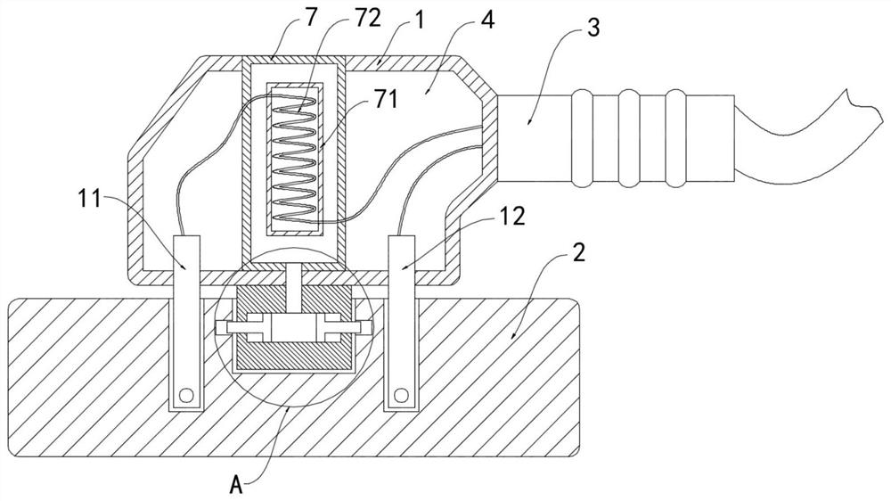
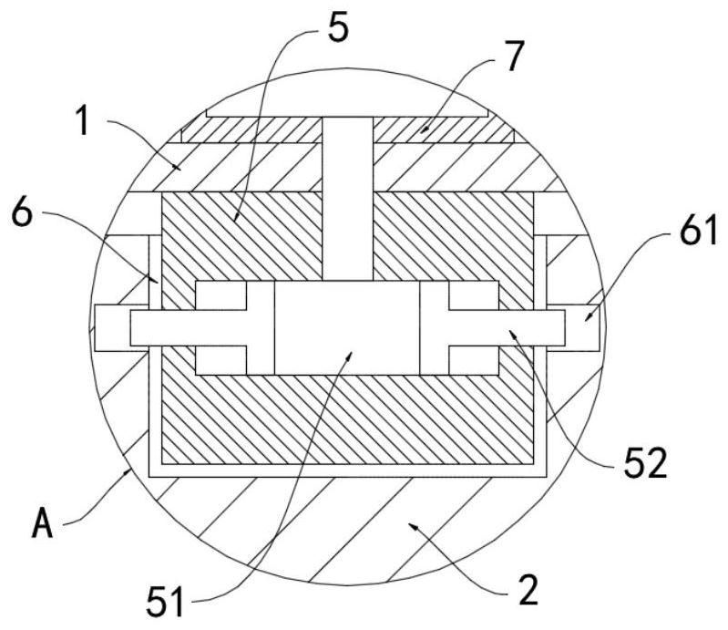
[0022] Such as Figure 1-2 As shown in the figure, an anti-off plug and socket based on the principle of thermal expansion includes a plug 1, a socket 2, a plug-in piece and an external wire 3 installed in the plug 1, a cavity 4 is provided in the plug 1, and the bottom of the plug 1 A clamping block 5 is fixedly connected, and the upper surface of the socket 2 is provided with a card slot 6 matching the clamping block 5;

[0023] The cavity 4 is provided with a transparent housing 7 filled with a mixture of nitrogen dioxide and dinitrogen tetroxide. The inner wall of the transparent housing 7 is fixedly connected with a heating tube 71, and the heating tube 71 is provided with a The heating wire 72 and the upper end of the transparent casing 7 are set through the top surface of the cavity 4. When the appliance is in use, the balance of the mixed gas of nitrogen dioxide and dinitrogen tetroxide moves to the direction of nitrogen dioxide generation, because the two Nitrogen ox...

Embodiment 2

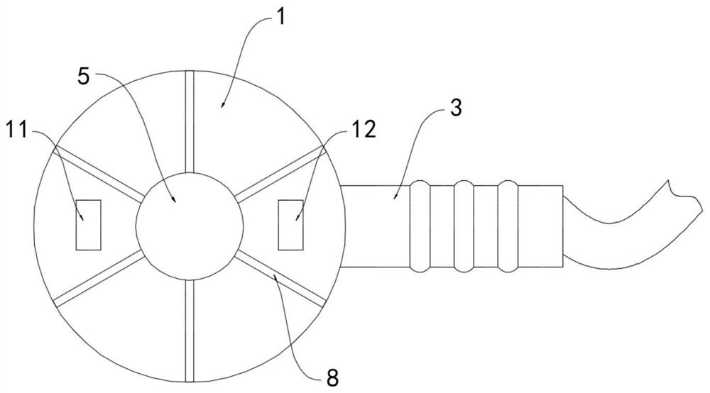
[0031] Such as image 3 As shown, the difference between this embodiment and Embodiment 1 is that the bottom of the plug 1 is fixedly connected with multiple water-absorbing expansion strips 8, and the multiple water-absorbing expansion strips 8 all extend from the center of the bottom surface of the plug 1 to form an annular array. arranged.

[0032] In this embodiment, a plurality of water-absorbing expansion strips 8 divide the contact surface between the plug 1 and the socket 2 into a plurality of mutually isolated sections, and the live line plug-in piece 11 and the neutral line plug-in piece 12 are located in different sections to prevent the socket from 2. When there is water stain on the surface, the water directly conducts the circuit between the live line plug-in piece 11 and the neutral line plug-in piece 12, and the risk of short circuit occurs, and when there is water stain on the surface of the socket 2, the water-absorbing expansion strip 8 can remove the water ...


PUM


Abstract

The invention belongs to the technical field of electrical equipment, and particularly relates to an anti-drop plug and socket based on a thermal expansion principle. The anti-drop plug comprises a plug, a socket, and plug sheets and an external wire which are arranged in the plug, wherein a cavity is arranged in the plug, and the bottom of the plug is fixedly connected with a clamping block. A clamping groove matched with the clamping block is formed in the upper surface of the socket, a transparent shell is arranged in the cavity, the transparent shell is filled with nitrogen dioxide and nitrogen tetroxide mixed gas, a heating pipe is fixedly connected to the inner side wall of the transparent shell, and an electric heating wire is arranged in the heating pipe; the plug sheets comprise alive wire plug sheet and a zero wire plug sheet, the live wire plug sheet is electrically connected with an external connection wire through an electric heating wire, and a sliding cavity is formed in the clamping block. According to the invention, the positions of the plug and the socket can be fixed and locked during working, so that the problem that the plug falls off due to artificial mistaken touch, collision or external wire tripping and the like is effectively avoided.

Description

technical field [0001] The invention belongs to the technical field of electrical equipment, and in particular relates to a detachment-proof plug and socket based on the principle of thermal expansion. Background technique [0002] Plugs and sockets are commonly used accessories for electrical equipment, which provide good convenience and safety performance for the daily use of electrical equipment. However, after a long period of use, traditional plugs often do not fit tightly with the socket due to the deformation of the plug-in blade. , resulting in the problem of poor contact during use, and plugs and sockets that are not tightly matched, it is very easy to cause the plug to fall off due to human error, collision, or external wiring, which not only brings troubles to users, but also exists Certain risks. [0003] Therefore, we propose an anti-off plug and socket based on the principle of thermal expansion to solve the above problems. Contents of the invention [0004...

Claims


Application Information

Patent Timeline
IPC IPC(8): H01R13/639H01R13/66H01R24/28H01R103/00
CPCH01R13/639H01R13/6608H01R24/28H01R2103/00
Inventor 付相勇
Owner 付相勇
Why Eureka
Try Eureka