Wall type landscape flowerpot rack based on air compression locking
A wall-type, flowerpot rack technology, applied in the field of flowerpot racks, can solve the problems of inability to occupy a large space, unable to fit on the wall, and use limitations, and achieves good use safety, avoids flowerpots from falling over, and operates handy effect
- Summary
- Abstract
- Description
- Claims
- Application Information
AI Technical Summary
Problems solved by technology
Method used
Image

Examples
Embodiment 1
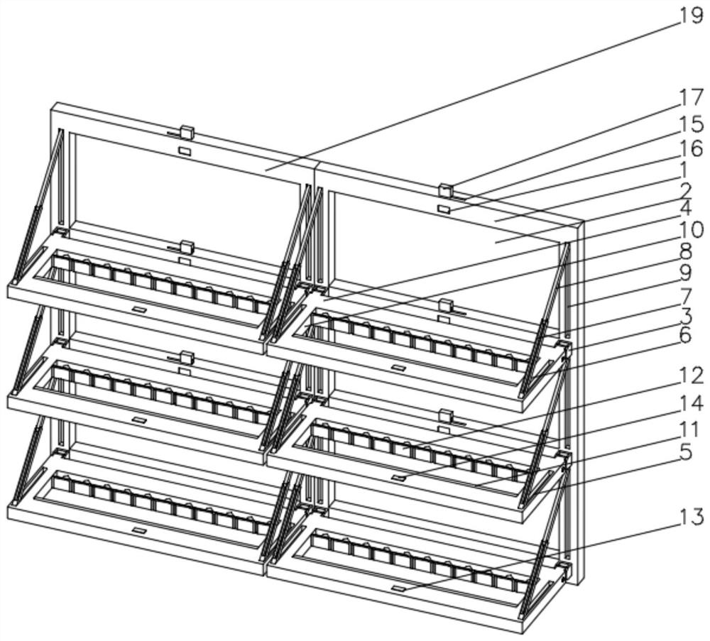
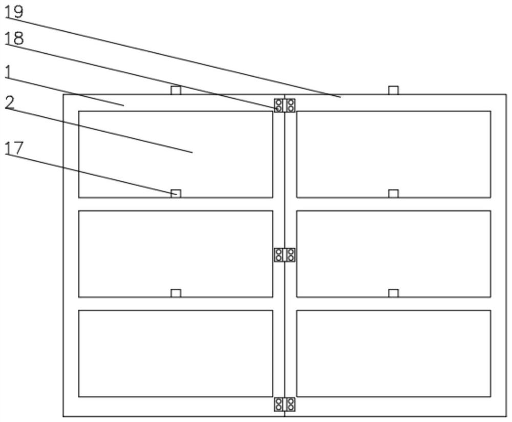
[0038] see Figure 1-6, the present invention provides a technical solution: a wall-type landscape flower pot stand based on air pressure locking, including a first fixing frame 1, a square hole 2 is opened on one side of the first fixing frame 1, and one side of the fixing frame 2 is located The part below the square hole 2 is fixedly connected with a swivel seat 3, and the inner wall of the swivel seat 3 is rotatably connected with a support plate 4. Both ends of the top of the support plate 4 are provided with a first storage groove 5, and the inner wall of the first storage groove 5 is far away from the swivel seat 3. One end is rotatably connected with the first connecting rod 6 through the turning pin, and the end of the first connecting rod 6 away from the first receiving groove 5 is provided with a matching groove 7, and the top of the inner wall of the matching groove 7 is rotatably connected with the second connecting rod 8 through the turning pin. One side of the fi...
Embodiment 2
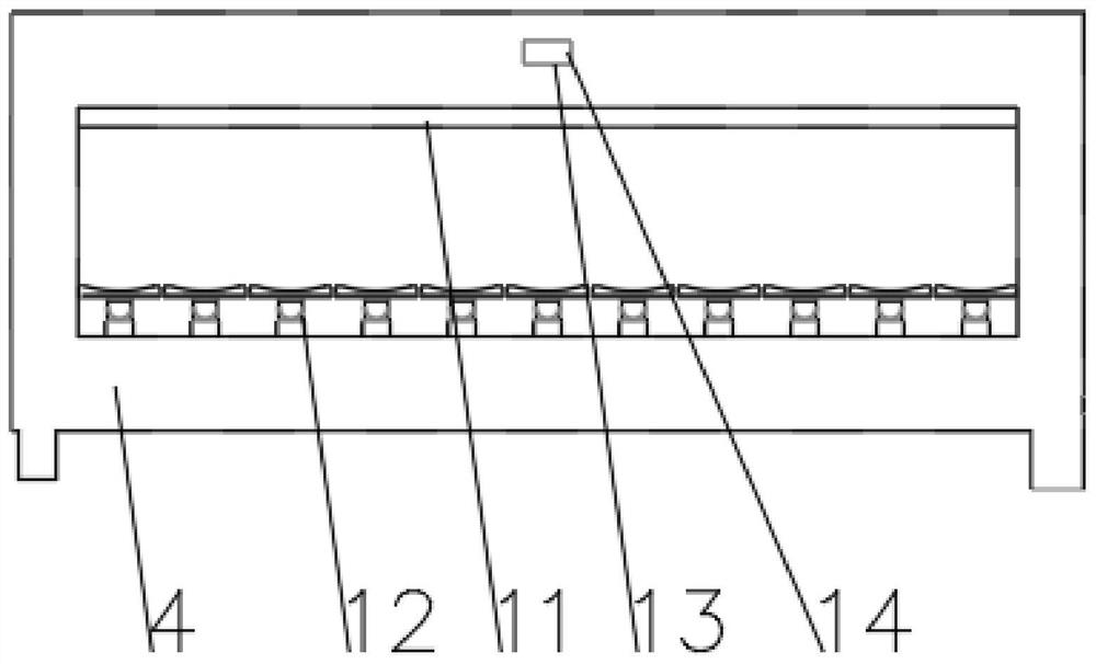
[0040] see Figure 1-7 On the basis of Embodiment 1, the present invention provides a technical solution: the positioning device 12 includes an air guide tube 121, the inner wall of one end of the air guide tube 121 is fixedly connected with a valve 122, and the end of the air guide tube 121 away from the valve 122 is connected with a shunt tube 123, and the shunt The inner wall of the air outlet of the pipe 123 is fixedly connected with a guide plate 124, the inner wall of the shunt pipe 123 close to the air outlet is slidably connected with a piston 125, one side of the piston 125 is fixedly connected with a guide rod 126, and the end of the guide rod 126 away from the piston 125 runs through the guide plate 124 and extends to the outside of the shunt pipe 123, the end of the guide rod 126 located at the outside of the shunt pipe 123 is provided with a through groove 127, the inner wall of the through groove 127 is fixedly connected with a rotating rod 128 through a rotating ...
PUM
 Abstract
Description
Claims
Application Information
 - R&D
- Intellectual Property
- Life Sciences
- Materials
- Tech Scout
- Unparalleled Data Quality
- Higher Quality Content
- 60% Fewer Hallucinations
Browse by: Latest US Patents, China's latest patents, Technical Efficacy Thesaurus, Application Domain, Technology Topic, Popular Technical Reports.
© 2025 PatSnap. All rights reserved.Legal|Privacy policy|Modern Slavery Act Transparency Statement|Sitemap|About US| Contact US: help@patsnap.com