Efficient suction filtration device of press

A technology of suction filter device and press, which is applied in the direction of filter circuit, filter separation, mobile filter element filter, etc., which can solve the problems of high purchase cost of filter cloth, affecting the production efficiency of the press, and large consumption

Pending Publication Date: 2020-11-20
上海奇宝智能科技有限公司
View PDF0 Cites 0 Cited by
  • Summary
  • Abstract
  • Description
  • Claims
  • Application Information

AI Technical Summary

Problems solved by technology

At present, the filter cloth is mostly cut into a single piece, and only the middle area of ​​each mold is in contact with the mud, and the surrounding area is not in contact with the mud, so the filtering effect is not achieved, which makes the utilization rate of the filter cloth lower.
And usually, when the press presses the ten-mode magnetic tile, the filter cloth needs to be replaced manually. In addition, the purchase cost of the filter cloth itself is relatively high, and the huge consumption of filter cloth will significantly increase the production cost of magnetic tile pressing.
In addition, it takes up to half an hour to change the cloth manually, and frequent replacement of filter cloth will seriously affect the production efficiency of the press

Method used


Image

  • Efficient suction filtration device of press
  • Efficient suction filtration device of press
  • Efficient suction filtration device of press

Examples


Embodiment 1

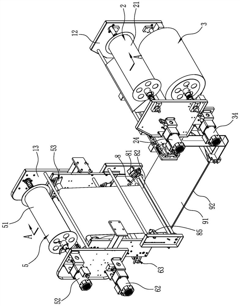
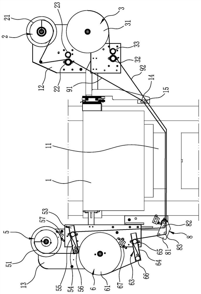
[0024] Embodiment one: if figure 1 , figure 2 and image 3 As shown, the high-efficiency suction filter device of the press includes a cloth releasing support 12 and a cloth receiving support 13 which are fixedly arranged relative to the upper die 11 of the press and are respectively located on both sides of the upper die 11 . The cloth releasing support 12 and the cloth receiving support 13 in this embodiment are fixed on the press base 1 of the press machine, but of course they can also be separated from the press base 1 and relatively fixedly arranged.

[0025] The cloth releasing support 12 is provided with a cloth releasing device 2 and a paper releasing device 3, and the cloth receiving support 13 is provided with a cloth receiving device 5 and a paper receiving device 6, and the cloth releasing device 2 and the cloth receiving device 5 is provided with a filter cloth 91 arranged below the upper die 11, and a filter paper 92 positioned below the filter cloth 91 is pro...

Embodiment 2

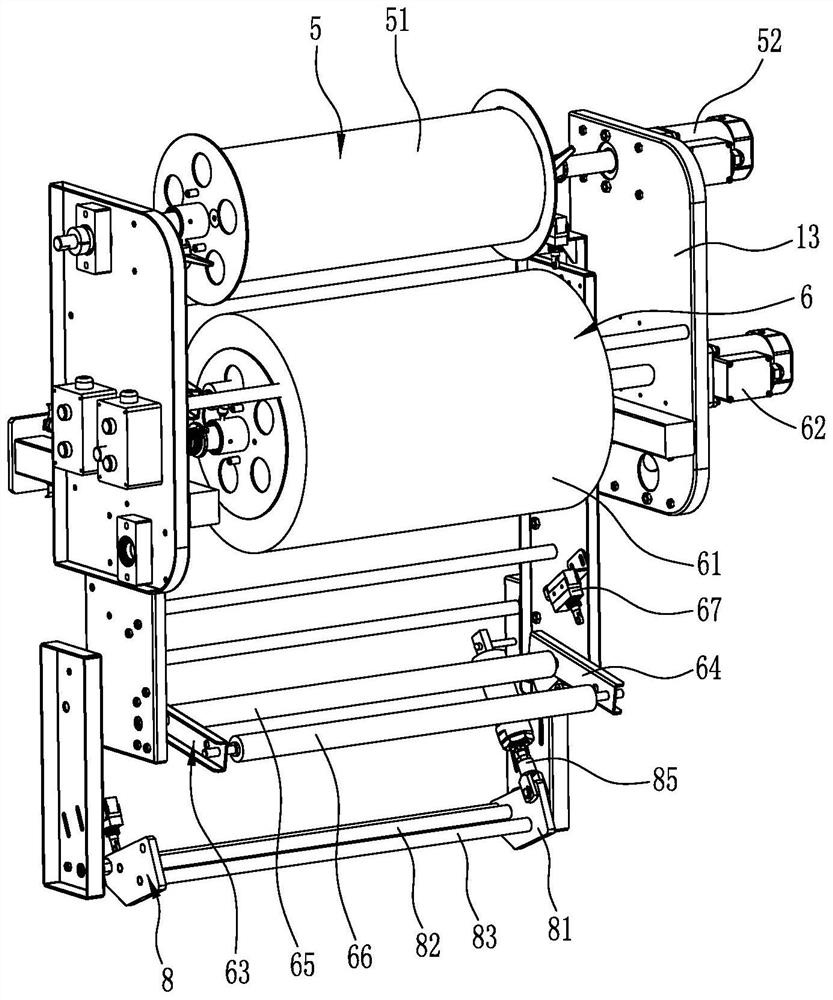
[0038] Embodiment two: if Figure 4 , Figure 5 and Figure 6 As shown, the difference between this embodiment and Embodiment 1 is: the yarn releasing device 4 is also provided on the cloth releasing support 12, the yarn receiving device 7 is provided on the cloth receiving support 13, and the yarn releasing device 4 and the yarn receiving device 7 is provided with a protective yarn 93 located between the upper die 11 and the filter paper 92 , and the yarn receiving elastic tensioning device 73 is provided on the cloth receiving support 13 . In this embodiment, adding the protective yarn 93 can reduce the abrasion of the filter cloth 91 by the upper die 11 , avoid replacement and damage, and improve the service life of the filter cloth 91 . Correspondingly, in the retractable pre-supporting device 8, the pre-supporting bracket 81 is provided with yarn supporting guide rollers 84, cloth supporting guide rollers 82 and paper supporting guides arranged in sequence along the dis...


PUM


Abstract

The invention discloses an efficient suction filtration device of a press. The efficient suction filtration device comprises a cloth unwinding bracket and a cloth winding bracket; a cloth unwinding device and a paper unwinding device are arranged on the cloth unwinding bracket; a cloth winding device and a paper winding device are arranged on the cloth winding bracket; filter cloth passing throughthe lower portion of an upper pressing die is arranged between the cloth unwinding device and the cloth winding device, and filter paper located below the filter cloth is arranged between the paper unwinding device and the paper winding device; the cloth winding bracket or the cloth unwinding bracket is provided with a winding-unwinding pre-supporting device, and the cloth winding bracket is provided with a cloth winding elastic tensioning device and a paper winding elastic tensioning device. Automatic replacement is achieved by winding and unwinding the filter cloth and the filter paper, andthe replacement efficiency is high. Due to the fact that the filter paper, which is low in price, is arranged below the filter cloth, which is high in price, pollution to the filter cloth is smaller,the filter cloth can be replaced from fifty molds to one hundred molds, and consumption of the filter cloth is obviously reduced. Meanwhile, the filter cloth and the filter paper can be seamlessly and continuously used in the length direction, and the utilization rate of the filter cloth is obviously increased.

Description

technical field [0001] The invention relates to the technical field of presses, in particular to a high-efficiency suction filter device for presses. Background technique [0002] In the production of the magnetic tile press, the pressing of each mold of the magnetic tile is accompanied by the filter mud of the filter cloth. The process of filter cloth filtering mud is also the process of filter cloth being polluted. At present, the filter cloth is mostly cut into a single piece for use, and only the middle area of ​​each mold is in contact with the mud, and the surrounding area is not in contact with the mud, so it cannot perform the filtering function, which makes the utilization rate of the filter cloth low. And usually, when the press presses ten-mode magnetic tiles, the filter cloth needs to be replaced manually. In addition, the purchase cost of the filter cloth itself is relatively high, and the huge consumption of filter cloth will significantly increase the product...

Claims


Application Information

Patent Timeline
Patent Type & Authority Applications(China)
IPC IPC(8): B01D36/00B01D33/04B01D33/42B01D33/80C02F11/123
CPCB01D33/04B01D33/42B01D33/80B01D33/804B01D36/003C02F11/123
Inventor 叶建平叶军叶建兵汪胜发李亚东何凯甘晓峰韦国钦徐辉
Owner 上海奇宝智能科技有限公司
Why Eureka
Try Eureka