Stirring tank overflow recovery system and control method thereof

A recovery system and control method technology, applied in the direction of mixer accessories, chemical instruments and methods, dissolution, etc., can solve the problems that the interference slurry cannot be overflowed and recovered, and achieve the effects of reducing labor intensity of workers, facilitating inhalation, and avoiding waste

Pending Publication Date: 2020-11-20
中冶北方(大连)工程技术有限公司
View PDF0 Cites 0 Cited by
  • Summary
  • Abstract
  • Description
  • Claims
  • Application Information

AI Technical Summary

Problems solved by technology

[0003] The purpose of the present invention is to provide a stirring tank overflow recovery system to

Method used


Image

  • Stirring tank overflow recovery system and control method thereof

Examples


Example Embodiment

[0023] The technical solutions in the embodiments of the present invention will be clearly and completely described below with reference to the accompanying drawings in the embodiments of the present invention:
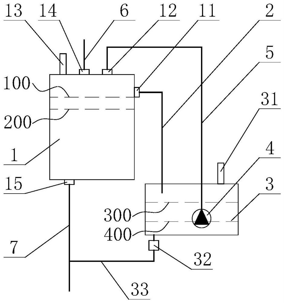
[0024] figure 1 The structure of the stirring tank overflow recovery system in the embodiment of the present invention is schematically shown. like figure 1 As shown, a stirring tank overflow recovery system provided by the present invention includes: a stirring tank 1, an overflow pipeline 2, an overflow buffer tank 3, a slurry pump 4 located in the overflow buffer tank 3, and a recovery Pipe 5. One end of the overflow pipe 2 is connected to the stirring tank 1 , and the other end extends into the overflow buffer tank 3 ; one end of the recovery pipe 5 is connected to the slurry pump 4 , and the other end is connected to the stirring tank 1 . The slurry in the stirring tank 1 of the stirring tank overflow recovery system can flow to the overflow buffer tank 3 thro...


PUM


Abstract

The invention discloses a stirring tank overflow recovery system and a control method thereof. The system comprises a stirring tank, an overflow buffer pool, an overflow pipeline, a recovery pipelineand a slurry pump located in the overflow buffer pool, one end of the overflow pipeline is connected with the stirring tank, the other end of the overflow pipeline extends into the overflow buffer pool, one end of the recovery pipeline is connected with the slurry pump, and the other end of the recovery pipeline is connected with the stirring tank. The overflow recovery of the interference slurryin the stirring tank is realized, the problem that the overflow slurry in the stirring tank needs to enter an accident pool and then is subjected to secondary treatment to be discharged is thoroughlysolved, the waste of materials is avoided, a large amount of personnel cost is saved, and the labor intensity of workers is reduced.

Description

technical field [0001] The invention relates to the technical field of mine filling slurry stirring, in particular to a stirring tank overflow recovery system and a control method thereof. Background technique [0002] At present, the agitation of mine filling slurry is an important part of filling preparation. When the feed volume of the vertical agitation tank is greater than the discharge volume or only feeds but not discharges, the slurry in the vertical agitation tank exceeds the maximum After the liquid level line, the excess slurry will directly overflow from the overflow port on the top edge of the mixing tank and be released into the emergency pool of the filling station. After the slurry in the emergency pool is deposited, it will be manually cleaned or washed with high-pressure water After pumping and discharging, the labor intensity is high, and it also causes a waste of materials. Contents of the invention [0003] The purpose of the present invention is to p...

Claims


Application Information

Patent Timeline
IPC IPC(8): B01F15/00
CPCB01F35/2212
Inventor 孙冠男巴家泓周育刘召胜
Owner 中冶北方(大连)工程技术有限公司
Why Eureka
Try Eureka