Electric brake exit point speed calculation method and electric brake exit control method and device

A speed calculation and control device technology, applied in the field of rail transit, can solve the problems of poor electric-air coordination control effect, reduce debugging difficulty and workload, etc., and achieve the effect of prolonging service life, reducing debugging difficulty and workload, and simple method

Inactive Publication Date: 2020-11-20
CRRC QINGDAO SIFANG ROLLING STOCK RES INST
View PDF5 Cites 5 Cited by
  • Summary
  • Abstract
  • Description
  • Claims
  • Application Information

AI Technical Summary

Problems solved by technology

[0011] The present invention aims at the above-mentioned problems such as universality and poor electro-pneumatic coordination control effect existing in the existing electric brake exit control process, and provides a method for calculating the speed of the electric brake exit point with universality and good electro-pneumatic coordination control effect, The electric brake exit control method and device can introduce the level information of the signal system into the calculation of the speed value of the exit point, realize the dynamic change of the exit point, have good universality, and greatly reduce the difficulty and workload of debugging

Method used

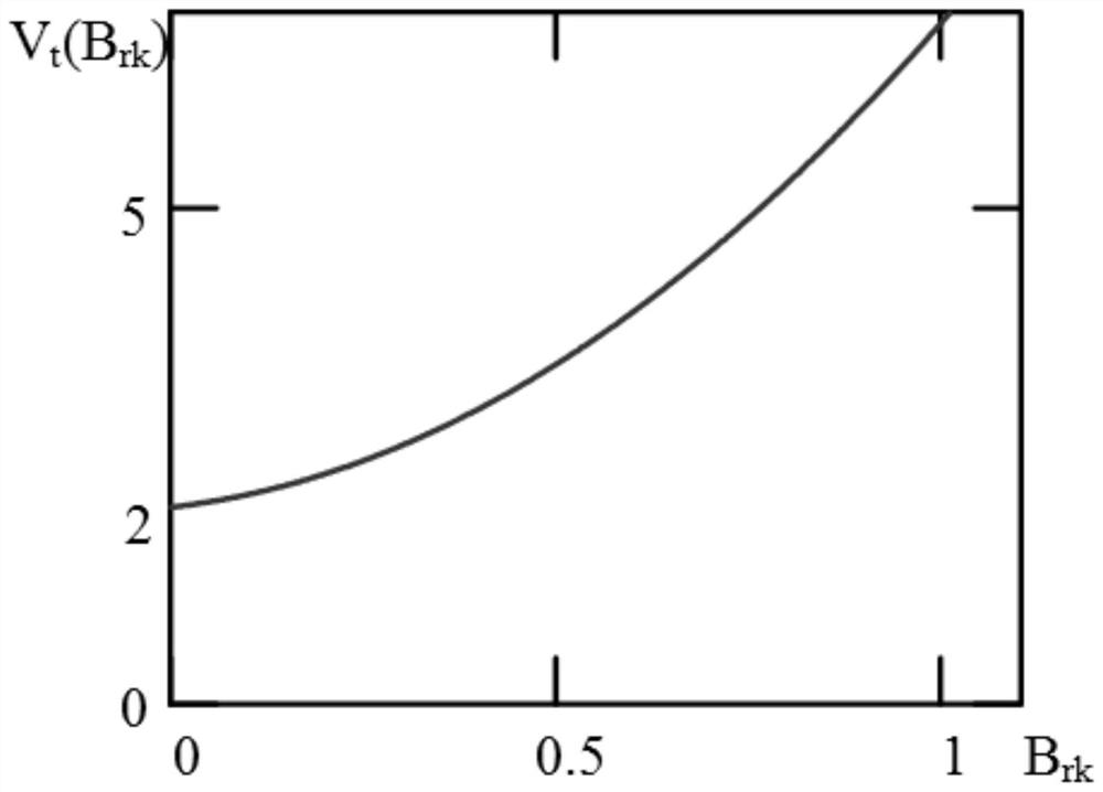
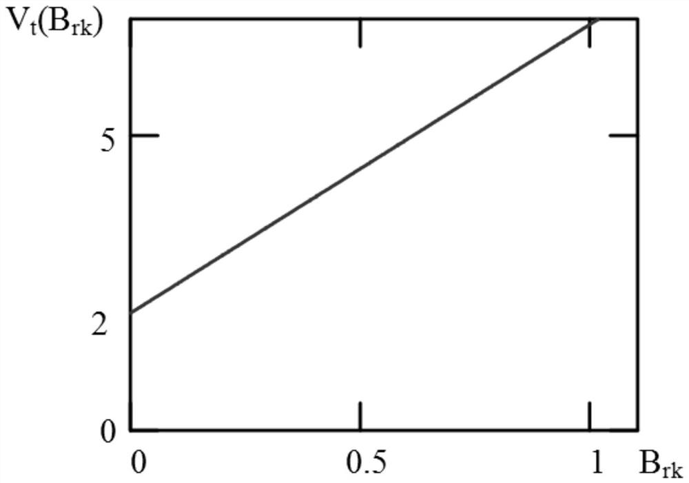
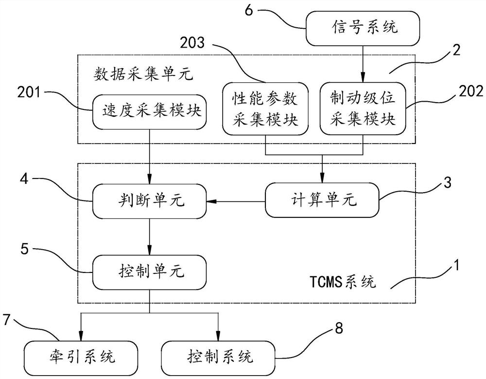

Image

  • Electric brake exit point speed calculation method and electric brake exit control method and device
  • Electric brake exit point speed calculation method and electric brake exit control method and device
  • Electric brake exit point speed calculation method and electric brake exit control method and device

Examples


Embodiment Construction

[0037] In the following, the present invention will be specifically described through exemplary embodiments. It should be understood, however, that elements, structures and characteristics of one embodiment may be beneficially incorporated in other embodiments without further recitation.

[0038] During the matching process of electric braking force and air braking force, considering from the perspective of user requirements, in order to prolong the service life of brake shoes, it is recommended to maximize the use of electric braking force. At the same time, from a technical point of view, in the process of electric The control accuracy of power is far inferior to that of electric braking force, so reducing the speed exit point of electric braking force as low as possible is conducive to improving the accuracy of benchmarking. In order to meet the above requirements, the present invention provides a method for calculating the speed at the exit point of the electric brake, a m...


PUM


Abstract

The invention relates to an electric brake exit point speed calculation method and an electric brake exit control method and device. The level information of the signal system is introduced into the calculation of an exit point speed value; dynamic change of an electric brake exit point is achieved, electric brake exit is controlled based on a TCMS system, on one hand, the universality problem ofan electric brake exit point control method can be solved, that is to say, electric-pneumatic matching parameters of each station can be changed at any time according to different level information ofa signal system; on the other hand, the signal system, the braking system and the traction system are matched with one another, the TCMS not only plays a role in forwarding, but also plays a good control role, and the debugging difficulty and workload are greatly reduced.

Description

technical field [0001] The invention belongs to the technical field of rail transit, and relates to electric braking technology, in particular to a method for calculating the speed of an electric braking exit point, an electric braking exit control method and a device. Background technique [0002] In the rail transit industry, only from the perspective of vehicles, if a train is capable of carrying passengers, it must go through strict type tests, routine tests and expert review processes for important nodes. Among them, the type test and routine test include vehicle assembly in the factory, static debugging, dynamic debugging and dynamic debugging of the main line, joint debugging with the signal system, 2000 kilometers no-load assessment test, etc. [0003] At present, conventional lines generally adopt the automatic driving (English: Automatic Train Operation, "ATO") mode of the signal system to carry passengers. After the debugging of the above-mentioned type test items...

Claims


Application Information

Patent Timeline
Patent Type & Authority Applications(China)
IPC IPC(8): B60T8/17B60T13/66
CPCB60T8/1705B60T13/662
Inventor 尹龙龙徐磊李文正王曙李德祥李然唐化勇张程
Owner CRRC QINGDAO SIFANG ROLLING STOCK RES INST
Why Eureka
Try Eureka