A UAV high-precision full-frame tilt photogrammetry device

An oblique photogrammetry and full-frame technology, which is applied in the direction of camera devices, motor vehicles, aircraft parts, etc., can solve the problems of high-definition camera damage, wide-angle real-time adjustment, etc., to achieve excellent results, reduce equipment costs, and strong applicability Effect

Active Publication Date: 2021-08-31
HENAN UNIVERSITY
View PDF8 Cites 1 Cited by
  • Summary
  • Abstract
  • Description
  • Claims
  • Application Information

AI Technical Summary

Problems solved by technology

[0005] The purpose of the present invention is to overcome the deficiencies that the unmanned aerial vehicle’s tilting photography device cannot adjust the angle and wide angle of its photography in real time, and cannot effectively reduce the vibration during the lifting process, resulting in the high-definition camera being easily damaged, and to design a high-precision unmanned aerial vehicle Full Frame Tilt Photogrammetry Device

Method used


Image

  • A UAV high-precision full-frame tilt photogrammetry device
  • A UAV high-precision full-frame tilt photogrammetry device
  • A UAV high-precision full-frame tilt photogrammetry device

Examples


Embodiment 1

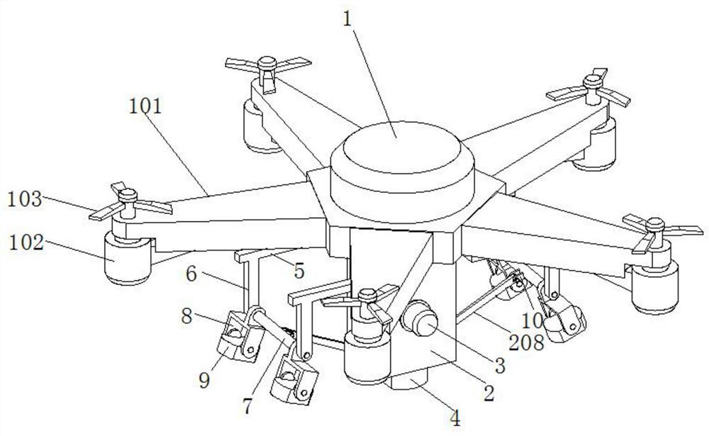
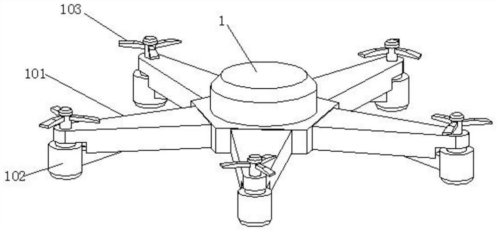
[0031]This embodiment 1 introduces a UAV high-precision full-frame tilt photogrammetry device, refer to the attached figure 1 , attached figure 2 And attached Figure 7 , which includes a UAV body 1, a number of rotor arms 101 are evenly connected to the UAV body 1, and a drive motor 102 is fixed on the lower surface of the outer end of each rotor arm 101, and the output shaft of the drive motor 102 passes through the rotor The upper end of the machine arm 101 is provided with a propeller 103 . When setting specifically, there are five rotorcraft arms 101 connected on the drone body 1 in this embodiment, and the five rotorcraft arms 101 are connected to the drone body 1 in an annular array, and the drone passes through A plurality of symmetrically arranged rotor arms 101 drive the mechanism together, so that the load-bearing capacity of the entire drone body 1 is not less than 8kg during flight, and the flight process is more balanced and stable. In addition, in order to s...

Embodiment 2

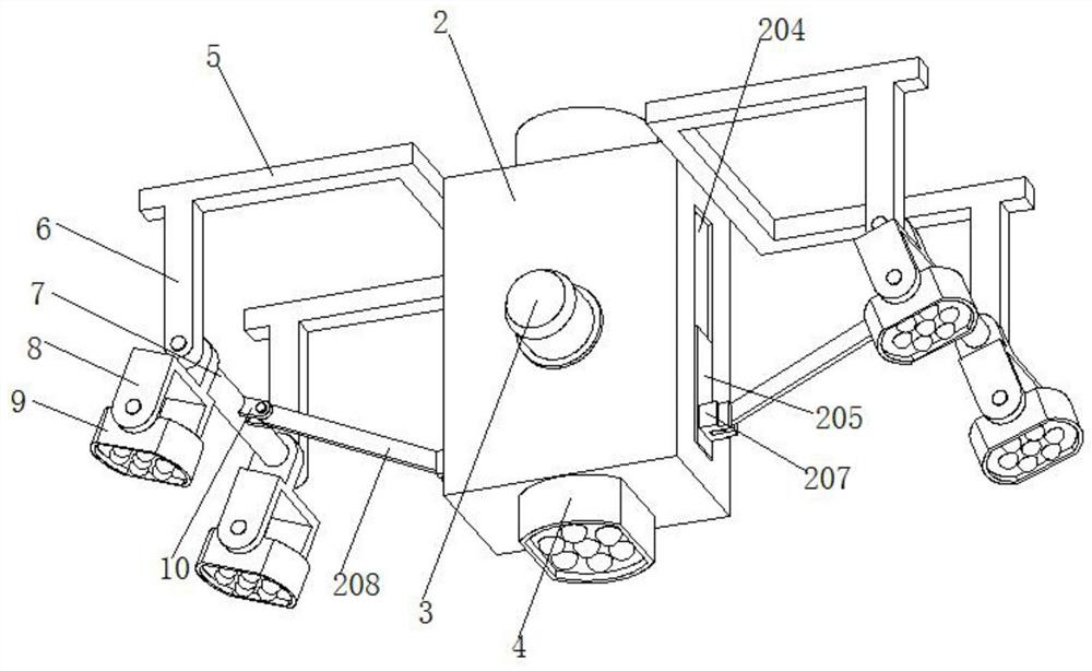
[0035] Embodiment 2 is a further improvement made on the basis of Embodiment 1, below in conjunction with the attached Figure 1~6 Explain it further.

[0036] Embodiment 2 discloses an improved UAV high-precision full-frame oblique photogrammetry device based on Embodiment 1. Refer to the attached figure 1 , attached figure 2 And attached Figure 7 , which includes a UAV body 1, a number of rotor arms 101 are evenly connected to the UAV body 1, and a drive motor 102 is fixed on the lower surface of the outer end of each rotor arm 101, and the output shaft of the drive motor 102 passes through the rotor The upper end of the machine arm 101 is provided with a propeller 103 . When setting specifically, there are five rotorcraft arms 101 connected on the drone body 1 in this embodiment, and the five rotorcraft arms 101 are connected to the drone body 1 in an annular array, and the drone passes through A plurality of symmetrically arranged rotor arms 101 drive the mechanism t...


PUM


Abstract

The invention relates to the technical field of unmanned aerial vehicle tilt photography detection, and specifically discloses a high-precision full-frame tilt photogrammetry device for unmanned aerial vehicles; it includes a drone body, and a number of rotor arms are uniformly connected to the drone body, each The lower surface of the outer end of the rotorcraft arm is fixed with a drive motor, and the output shaft of the drive motor passes through the upper end of the rotorcraft arm to be provided with a propeller. The center of the lower surface of the drone body is connected with a rectangular block, and the front side of the rectangular block is fixed. There is an adjusting motor, a rotating chamber is arranged inside the rectangular block, and a large gear is arranged in the middle of the rotating chamber; the device of the present invention can perform real-time adjustment of the photography angle and wide angle in actual use; and it can be realized simultaneously by an adjusting motor The adjustment of the shooting angles of the four second high-definition cameras does not require an adjustment motor at the end of each second high-definition camera, which greatly reduces the cost of equipment, and more importantly, effectively reduces the load of the entire drone.

Description

technical field [0001] The invention relates to the technical field of unmanned aerial vehicle oblique photography detection, and specifically discloses a high-precision full-frame oblique photogrammetry device for unmanned aerial vehicles. Background technique [0002] Oblique photography technology is a high-tech developed in the field of international surveying and mapping in recent years. It overturns the previous limitation that orthophoto images can only be taken from a vertical angle. By carrying multiple high-definition cameras on the same flight platform, its high-definition Set it to five, so that images can be collected from five different angles such as one vertical and four oblique at the same time, which introduces users to a real and intuitive world that conforms to human vision. Object texture information can also generate a real 3D city model through advanced positioning, fusion, modeling and other technologies. [0003] At present, the five high-definition...

Claims


Application Information

Patent Timeline
Patent Type & Authority Patents(China)
IPC IPC(8): B64C39/02B64D47/08B64C25/62G01C11/02
CPCB64C25/62B64C39/02B64D47/08G01C11/02
Inventor 夏浩铭赵威陈优括秦耀辰
Owner HENAN UNIVERSITY
Why Eureka
Try Eureka