
Mining rescue unmanned aerial vehicle

A technology for unmanned aerial vehicles and mines, which is applied in the field of unmanned aerial vehicles, can solve the problems of damaged rotor, poor rescue effect, and delayed rescue timing, etc., to achieve the effect of improving physical strength, facilitating flight, and improving survival rate

Pending Publication Date: 2020-11-20
XIAN TECHNOLOGICAL UNIV
View PDF6 Cites 3 Cited by
  • Summary
  • Abstract
  • Description
  • Claims
  • Application Information

AI Technical Summary

Problems solved by technology

There are many types of coal mine roadways. Different roadway surfaces are affected by different types, and the shape, cross-sectional size, and degree of stability of the roadway are very different. Especially during the disaster period, the narrow roadway surface is full of obstacles, and it is difficult for the robot to move forward underground, resulting in the detection robot. move on, thereby failing to provide a comprehensive survey of the downhole environment
[0004] China Patent No. 201620141951.5, named as a multi-axis rotor underground robot system, although the system can be applied to underground inspection and accident rescue, but in the mine roadway, the rotor of the multi-axis rotor underground robot does not have any protective devices, making the rotor impossible To avoid collision with the roadway wall or damage to the rotor by falling gravel in the roadway, the multi-axis rotor robot cannot fly; at the same time, the multi-axis rotor robot cannot carry rescue materials, and the rescue effect is poor; and during rescue, The timing of rescue is delayed because medical personnel often cannot arrive at the rescue site in time

Method used


Image

  • Mining rescue unmanned aerial vehicle
  • Mining rescue unmanned aerial vehicle
  • Mining rescue unmanned aerial vehicle

Examples


Embodiment Construction

[0044] The following will clearly and completely describe the technical solutions in the embodiments of the present invention with reference to the accompanying drawings in the embodiments of the present invention. Obviously, the described embodiments are only some, not all, embodiments of the present invention. Based on the embodiments of the present invention, all other embodiments obtained by persons of ordinary skill in the art without making creative efforts belong to the protection scope of the present invention.

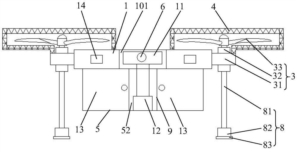
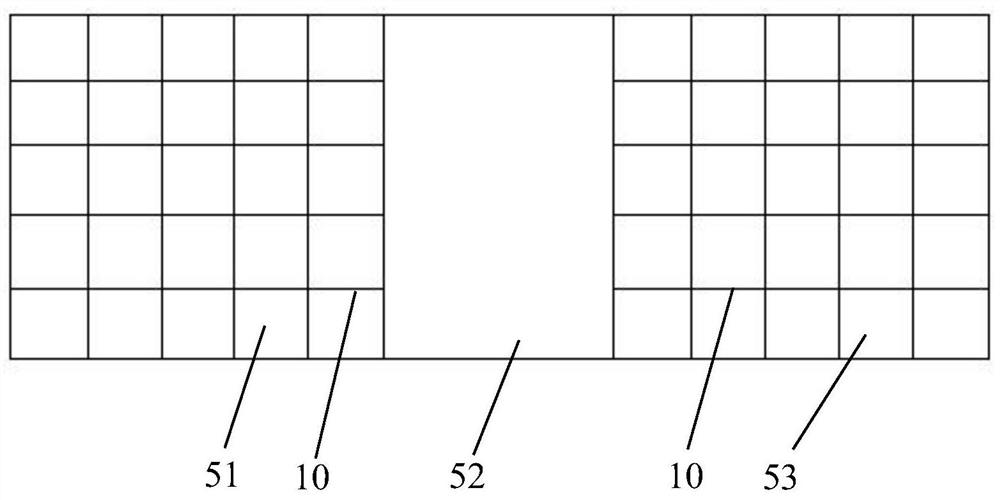
[0045] The embodiment of the present invention discloses a mining rescue drone, including:

[0046] Body 1,

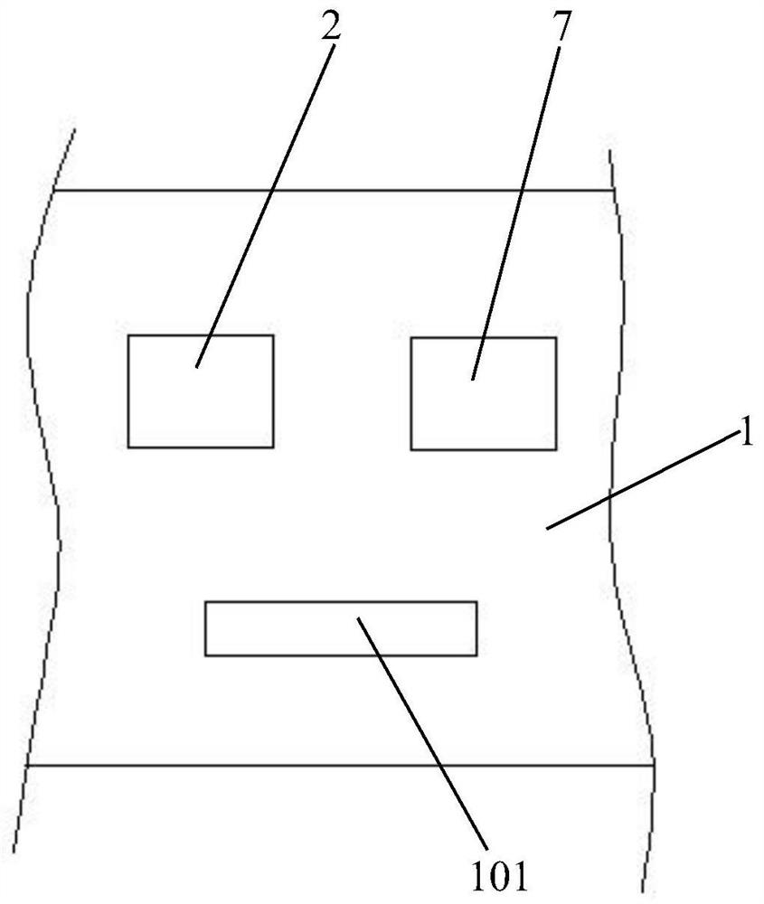
[0047] The main controller 2, the main controller 2 is set inside the body 1, and is connected to the external wireless remote controller through wireless communication;

[0048] Power device 3, there are multiple power devices 3, and the multiple power devices 3 are evenly distributed on both sides of the body 1, and are all electrically connected to...


PUM


Abstract

The invention discloses a mining rescue unmanned aerial vehicle. The unmanned aerial vehicle comprises a vehicle body, a main controller, power devices, protective net covers, a storage box, a camera,and a battery, wherein the main controller is arranged in the vehicle body and is in wireless communication connection with an external wireless remote controller; the multiple power devices are evenly distributed on the two sides of the vehicle body and electrically connected with the main controller; the number of the protective net covers is multiple, the multiple protective net covers are allfixedly connected with the vehicle body, and each power device is arranged in the corresponding protective net cover; a top end of the storage box is fixedly connected with the bottom end of the vehicle body; the camera is fixedly mounted on the front side of the vehicle body and is electrically connected with the main controller; and the battery supplies power to electrical equipment of the unmanned aerial vehicle. By arranging the protective net covers, problems that the power devices are affected by falling stones and collide with the wall of an underground roadway are effectively solved,the unmanned aerial vehicle can fly normally, the storage box is arranged, rescue materials can be carried, and corresponding water sources, food and medicine are provided for to-be-rescued personnel.

Description

technical field [0001] The invention relates to the technical field of unmanned aerial vehicles, and more specifically relates to a mining rescue unmanned aerial vehicle. Background technique [0002] At present, drones have been widely used in aerial photography, agriculture, forestry, fire, monitoring and early warning. The miniaturization, high mobility and portability of drones have shown very high adaptability in the above fields. Underground disasters in coal mines include gas explosions, water inrush and other accidents. Once an accident occurs, the communication facilities are damaged, underground power outage measures, underground roadways, equipment damage and air environment cannot be known, which will help the formulation of post-disaster rescue plans and the safety of rescuers. pose great challenges. The current underground accident rescue generally depends on the professional knowledge and experience of experts to judge, evaluate the underground environment an...

Claims


Application Information

Patent Timeline
Patent Type & Authority Applications(China)
IPC IPC(8): B64D9/00B64D27/24B64D45/00B64D47/04B64D47/02B64D47/08B64C27/08B64C27/14B64C27/20B64C25/10
CPCB64D9/00B64D27/24B64D45/00B64D47/04B64D47/02B64D47/08B64C27/08B64C27/14B64C27/20B64C25/10B64U10/10B64U2101/00B64U50/19Y02T50/60
Inventor 易华辉周巍章阳
Owner XIAN TECHNOLOGICAL UNIV
Learn More