Laminated plate lifting appliance and steel beam

A technology of laminated slabs and spreaders, which is applied in the field of spreaders and steel beams, can solve problems such as few stress points at the top, poor stability of laminated slabs, and swaying, etc., to expand the range, promote stability, even force effect

Pending Publication Date: 2020-11-20
CHINA CONSTR SCI & TECH CO LTD
View PDF1 Cites 4 Cited by
  • Summary
  • Abstract
  • Description
  • Claims
  • Application Information

AI Technical Summary

Problems solved by technology

A cross-combined laminated slab hanger in the above-mentioned patent has the following disadvantages: the overall device adopts a cross structure lifting method, and the laminated slab in this way cannot maintain stability well during the lifting process, and the top of the hoisting There are fewer stress points, and there will be shaking during translation

Method used


Image

  • Laminated plate lifting appliance and steel beam
  • Laminated plate lifting appliance and steel beam
  • Laminated plate lifting appliance and steel beam

Examples


Embodiment 1

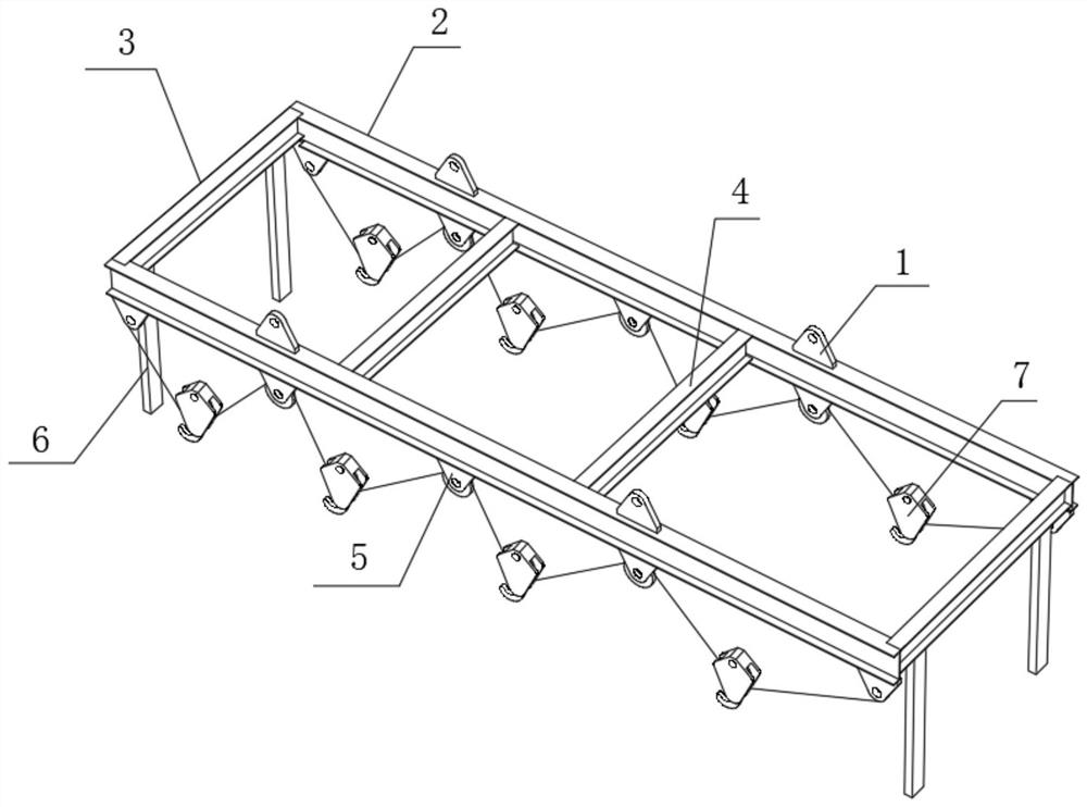
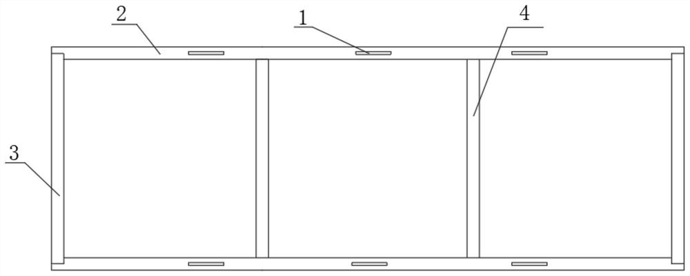
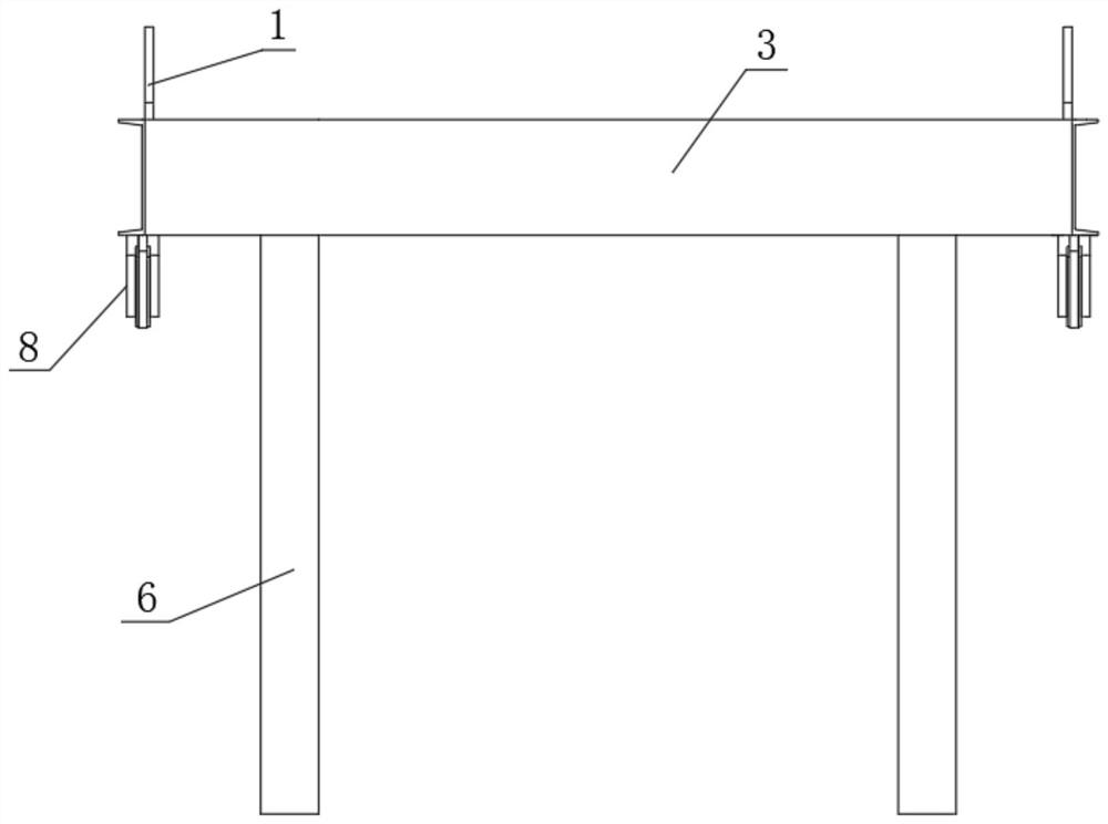
[0033] Laminated slab spreaders and beams, such as Figure 1-6 As shown, two first I-beams 2 and two second I-beams 3 are included, welding grooves 12 are opened at both ends of the two first I-beams 2, and two second I-beams The two ends of 3 are respectively welded to the welding grooves 12 of the two first I-beams 2, the two first I-beams 2 and the two second I-beams 3 form a rectangular frame structure, and the two first I-beams Two welding holes are respectively opened on the top outer wall of the beam 2, and a hanging plate 1 is welded on the inner wall of each welding hole, and a hanging hole is opened on one side outer wall of each hanging plate 1, and the two first I-beams The outer walls of the bottom at both ends of 2 are fixed with triangular support plates by bolts, and the outer walls of one side of each triangular support plate are inserted with fixed shafts, and the outer bottom walls of the two first I-beams 2 are welded with fixed The pulley assembly 5 has a...

Embodiment 2

[0040] Laminated slab spreaders and beams, such as Figure 8 As shown, in order to facilitate the lifting of wallboards of different lengths; this embodiment makes the following improvements on the basis of embodiment 1: preferably, two second I-beams 3 with channel steel 6 are replaced with no The two second I-beams 3 of the channel steel 6 effectively expand the scope of the overall structure for hoisting objects, especially for hoisting wallboards of different lengths.

[0041] When this embodiment is in use, the lifting requirements for stacked plates of different lengths are effectively met by the two second I-beams 3 without the channel steel 6 .


PUM


Abstract

The invention discloses a laminated plate lifting appliance and a steel beam, and relates to the technical field of lifting appliances and steel beams. The stability problem of lifting of the liftingappliance is solved, the laminated plate lifting appliance specially comprises two first I-shaped steels and two second I-shaped steels, wherein the two ends of the two first I-shaped steels are provided with welding grooves, the two ends of the two second I-shaped steels are welded with the welding grooves of the two first I-shaped steels correspondingly, the two first I-shaped steels and the twosecond I-shaped steels form a rectangular frame structure, the top outer walls of the two first I-shaped steels are each provided with two welding holes, and a lifting plate is welded on the inner wall of each welding hole; and the outer wall of one side of each lifting plate is provided with a lifting hole, and triangular supporting plates are fixed on the outer walls of the bottoms of the two ends of the two first I-shaped steels through bolts. The problem of translational shaking of a laminated plate caused by less hoisting points of a traditional lifting appliance is solved, and the lifting stability of the laminated plate is effectively ensured through a fixed pulley assembly and a movable pulley hook assembly.

Description

technical field [0001] The invention relates to the technical field of a spreader and a steel beam, in particular to a spreader for a laminated plate and a steel beam. Background technique [0002] The laminated slab is a better structural form of the combination of prefabricated and cast-in-place concrete in residential industrial components, including prefabricated prestressed thin slabs and upper cast-in-place concrete layers, which are combined into a whole and work together. This kind of laminated floor has the advantages of integrity of cast-in-place floor, high rigidity, good crack resistance, no increase in steel consumption, saving formwork, etc. Since the cast-in-place floor slab does not need formwork, there are also large prefabricated concrete partition walls that can be hoisted at the same time during the structural construction stage, so that the decoration project can be inserted in advance and the construction period of the entire project can be shortened. ...

Claims


Application Information

Patent Timeline
Patent Type & Authority Applications(China)
IPC IPC(8): B66C1/14
CPCB66C1/14
Inventor 贺树阳谢洪彬王伟王士响
Owner CHINA CONSTR SCI & TECH CO LTD
Why Eureka
Try Eureka