Cap opening device for ampoule bottles

A cap-opening device and ampoules technology, which is applied to bottle/container caps, electric operation devices, manual cutting devices, etc., can solve the problems of labor-intensive and low work efficiency, and achieve the advantages of improving work efficiency, simple operation and manpower saving. Effect

Active Publication Date: 2020-11-20
HUNAN PROVINCIAL TUMOR HOSPITAL
View PDF10 Cites 9 Cited by
  • Summary
  • Abstract
  • Description
  • Claims
  • Application Information

AI Technical Summary

Problems solved by technology

[0006] In order to overcome the disadvantages that only one ampoule bottle can be uncapped at a time when the above-mentioned method is operated, the work efficiency is low, and manual operation of the opening and opening of the bottle mouth is re

Method used


Image

  • Cap opening device for ampoule bottles
  • Cap opening device for ampoule bottles
  • Cap opening device for ampoule bottles

Examples


Embodiment 1

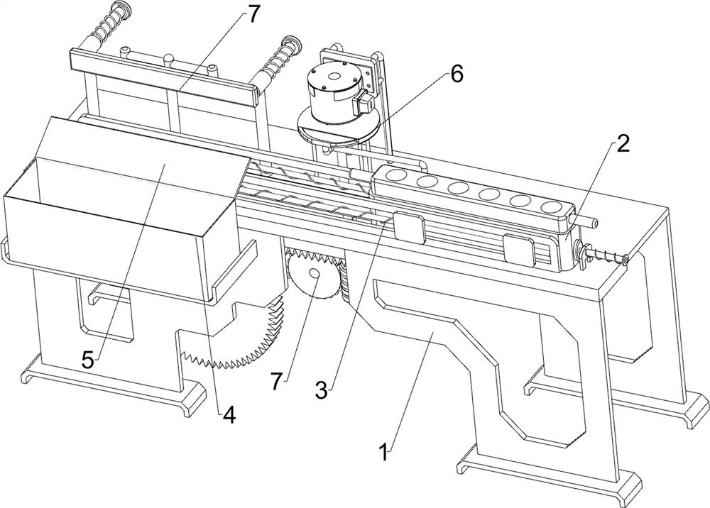
[0024] An ampoule bottle cap opening device, such as Figure 1-2 and Figure 4 As shown, it includes an installation table 1, a sliding frame 2, a first return spring 3, a collection frame 4 and a swash plate 5. The top of the installation table 1 is slidably connected with a sliding frame 2, and there is a certain distance between the sliding frame 2 and the installation table 1. A first return spring 3 is connected between the sliding frame 2 and the installation table 1, a collection frame 4 is connected to the left side of the installation table 1, a sloping plate 5 is connected to the top of the collection frame 4, and a movable cutting assembly 6 and For the pusher assembly 7 , a movable cutting assembly 6 is arranged between the installation table 1 and the sliding frame 2 , and a pusher assembly 7 is arranged on the installation table 1 .

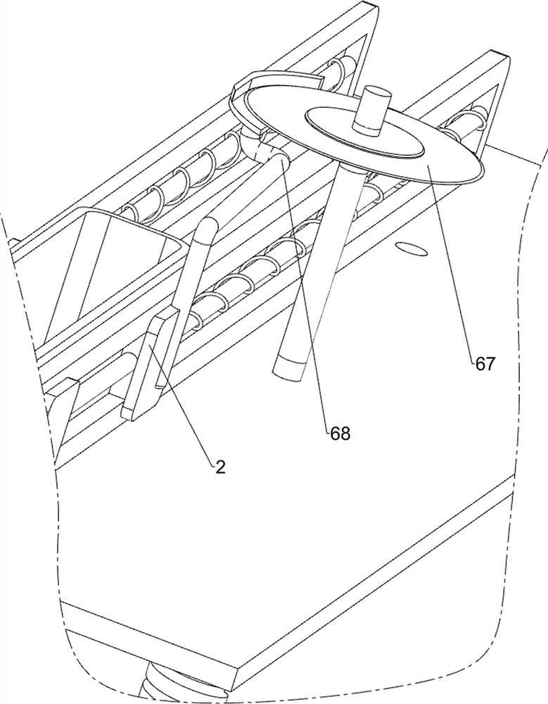
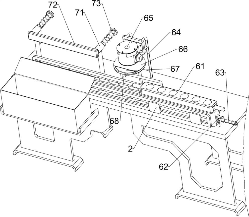
[0025] The moving cutting assembly 6 includes a placing frame 61, a sliding rod 62, an elastic member 63, a fixing frame 64, a dr...

Embodiment 2

[0029] On the basis of Example 1, as image 3 As shown, it also includes a drive assembly 8, the drive assembly 8 includes a guide rail 81, a transmission rack 82, a compression spring 83, a shaft 84, a worm 85, a worm wheel 86 and a toothless gear 87, and the bottom of the sliding frame 2 is connected with a guide rail 81 The guide rail 81 is slidably connected with a transmission rack 82, and a compression spring 83 is connected between the transmission rack 82 and the guide rail 81. The elastic force of the compression spring 83 is greater than that of the first return spring 3, and the output shaft of the drive motor 65 is connected to There is a shaft 84, the shaft 84 is connected with a worm 85 through the installation table 1, a worm wheel 86 is rotatably connected in the middle of the installation table 1, the worm wheel 86 cooperates with the worm 85, and the left side of the installation table 1 is rotatably connected with a toothless gear 87. The tooth-missing gear ...


PUM


Abstract

The invention relates to a cap opening device, in particular to a cap opening device for ampoule bottles. The cap opening device for the ampoule bottles aims to be capable of uncapping a plurality ofampoule bottles at one time, improving working efficiency and saving manpower. In order to achieve the technical aim, the cap opening device for the ampoule bottles comprises a mounting table, a firstreturn spring, a collecting frame, a movable cutting assembly and a pushing assembly, wherein the top of the mounting table is connected with a sliding frame in a sliding manner, and a certain friction force is arranged between the sliding frame and the mounting table; the first return spring is connected between the sliding frame and the mounting table; the collecting frame is connected to one side of the mounting table, and an inclined plate is connected to the top of the collecting frame; the movable cutting assembly is arranged between the mounting table and the sliding frame; and the pushing assembly is arranged on the mounting table. According to the cap opening device for the ampoule bottles, the movable cutting assembly and the pushing assembly are matched to operate so as to achieve the effect of uncapping the ampoule bottles.

Description

technical field [0001] The invention relates to a cap opening device, in particular to an ampoule bottle cap opening device. Background technique [0002] In the storage of modern medical liquids, ampoules are usually used. Ampoules are glass containers that can be used to hold medicinal liquids. The capacity is usually one to twenty-five milliliters. It can also be used to make the packaging of oral liquid. When the ampoule bottle needs to take out the liquid medicine inside, the ampoule bottle needs to be opened, and then the liquid medicine in the ampoule bottle can be taken out for use. . [0003] At present, the way to open the ampoule bottle is usually to open a small mouth at the bottle mouth position of the ampoule bottle by manually using a saw blade, and then the user will break the bottle mouth of the ampoule bottle to complete the cap opening. The above method During operation, only one ampoule bottle can be opened at one time, and the work efficiency is low, a...

Claims


Application Information

Patent Timeline
IPC IPC(8): B67B7/46B67B7/92
CPCB67B7/38B67B7/92Y02W30/60
Inventor 曾小梅
Owner HUNAN PROVINCIAL TUMOR HOSPITAL
Why Eureka
Try Eureka