Multifunctional flood-fighting bridge equipment for roads and bridges
A multi-functional technology for bridges, applied in bridges, bridge forms, vertical bridges, etc., can solve problems such as lack of anti-flood bridge equipment, bridges cannot be used normally, etc., and achieve the effect of increasing gravity
- Summary
- Abstract
- Description
- Claims
- Application Information
AI Technical Summary
Problems solved by technology
Method used
Image
Examples
specific Embodiment approach 1
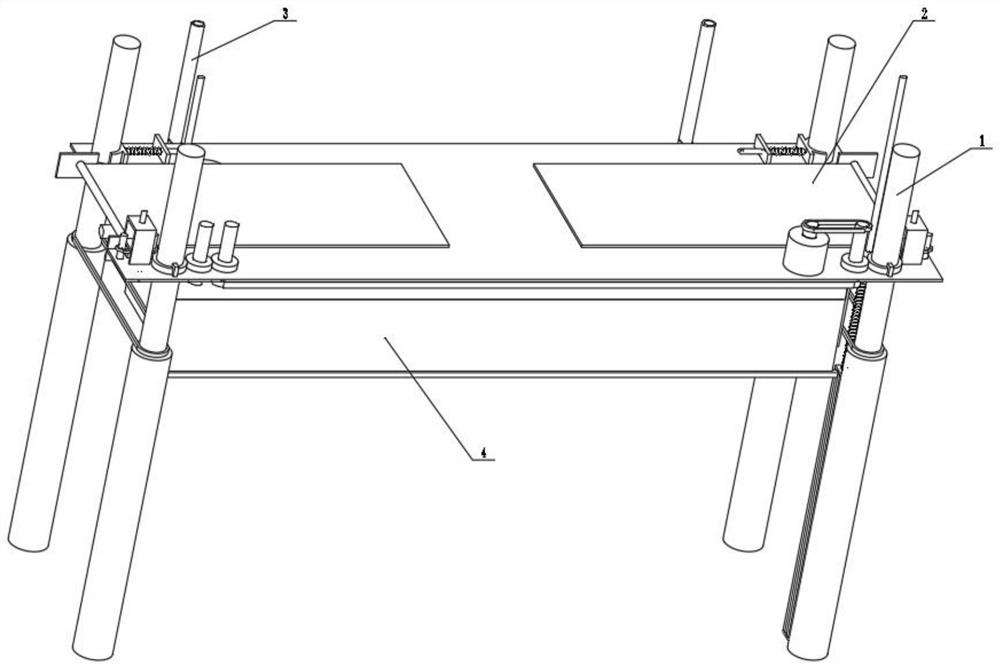
[0037] Combine below figure 1 , figure 2 , image 3 , Figure 4 , Figure 5 , Image 6 , Figure 7 , Figure 8 , Figure 9 , Figure 10 , Figure 11 , Figure 12 , Figure 13 , Figure 14 , Figure 15 , Figure 16 , Figure 17 , Figure 18 , Figure 19 , Figure 20 , Figure 21 Describe this embodiment, the present invention relates to a kind of anti-flood bridge equipment, more specifically a kind of multifunctional anti-flood bridge equipment for road bridges, including raising mechanism 1, bridge body extension mechanism 2, downpressing mechanism 3, flood blocking mechanism Mechanism 4, the equipment can make the bridge rise, the equipment can extend the length of the bridge deck and continue to overlap the two banks when the bridge rises, the equipment can block the water flow, and the equipment can increase the gravity on the underside of the bridge face when blocking the water flow.
[0038] The raising mechanism 1 is connected with the bridge extensi...
specific Embodiment approach 2
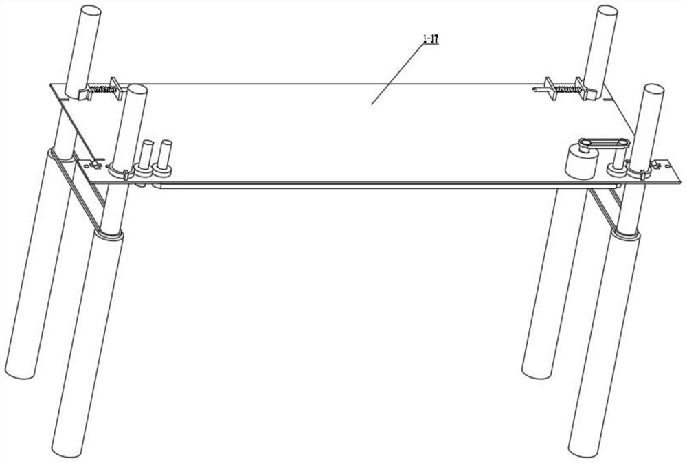
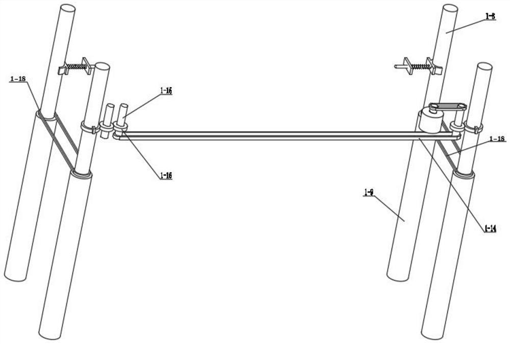
[0040] Combine below figure 1 , figure 2 , image 3 , Figure 4 , Figure 5 , Image 6 , Figure 7 , Figure 8 , Figure 9 , Figure 10 , Figure 11 , Figure 12 , Figure 13 , Figure 14 , Figure 15 , Figure 16 , Figure 17 , Figure 18 , Figure 19 , Figure 20 , Figure 21 Describe this embodiment, this embodiment will further explain the first embodiment, the lifting mechanism 1 includes a power motor 1-1, a motor shaft 1-2, a belt a1-3, a transmission shaft a1-4, a transmission gear a1- 5. Transmission gear b1-6, gear limit block 1-7, threaded column 1-8, internal thread column 1-9, threaded column limit block 1-10, limit shaft 1-11, limit plate 1-12 , limit spring 1-13, belt b1-14, transmission shaft b1-15, transmission gear c1-16, bridge deck 1-17, belt c1-18, power motor 1-1 is connected with motor shaft 1-2, and the motor Shaft 1-2 is frictionally connected with belt a1-3, belt a1-3 is frictionally connected with transmission shaft a1-4, transmi...
specific Embodiment approach 3
[0042] Combine below figure 1 , figure 2 , image 3 , Figure 4 , Figure 5 , Image 6 , Figure 7 , Figure 8 , Figure 9 , Figure 10 , Figure 11 , Figure 12 , Figure 13 , Figure 14 , Figure 15 , Figure 16 , Figure 17 , Figure 18 , Figure 19 , Figure 20 , Figure 21 Describe this embodiment, this embodiment will further explain the first embodiment, the bridge body extension mechanism 2 includes the rotating shaft a2-1, the rotating belt a2-2, the rotating shaft b2-3, the friction wheel 2-4, the rotating shaft c2-5, connection plate a2-6, rotation limit shaft 2-7, connection plate b2-8, rotation limit spring 2-9, rotation limit block 2-10, rotation bridge deck 2-11, rotation axis a2 -1 is frictionally connected with the rotating belt a2-2, the rotating belt a2-2 is frictionally connected with the rotating shaft b2-3, the rotating shaft b2-3 is connected with the bridge deck 1-17 bearing, and the friction wheel 2-4 is connected with the rotating ...
PUM
 Abstract
Description
Claims
Application Information
 - R&D
- Intellectual Property
- Life Sciences
- Materials
- Tech Scout
- Unparalleled Data Quality
- Higher Quality Content
- 60% Fewer Hallucinations
Browse by: Latest US Patents, China's latest patents, Technical Efficacy Thesaurus, Application Domain, Technology Topic, Popular Technical Reports.
© 2025 PatSnap. All rights reserved.Legal|Privacy policy|Modern Slavery Act Transparency Statement|Sitemap|About US| Contact US: help@patsnap.com


