Attenuator and differential voltage probe

An attenuator and attenuation circuit technology, applied in the field of electronics, can solve the problems of distortion of differential voltage probe measurement results and poor stability of the attenuator.

Pending Publication Date: 2020-11-20
SHENZHEN ZHIYONG ELECTRONICS CO LTD
View PDF0 Cites 2 Cited by
  • Summary
  • Abstract
  • Description
  • Claims
  • Application Information

AI Technical Summary

Problems solved by technology

[0004] The invention provides an attenuator and a differential voltage probe to solve the problems of poor stability of the attenuator and distortion of the measurement results of the differential voltage probe in the prior art when an adjustable capacitor is used to adjust the amplitude-frequency characteristics

Method used


Image

  • Attenuator and differential voltage probe
  • Attenuator and differential voltage probe
  • Attenuator and differential voltage probe

Examples


Embodiment Construction

[0048] In order to make the object, technical solution and advantages of the present invention clearer, the present invention will be further described in detail below in conjunction with the accompanying drawings and embodiments. It should be understood that the specific embodiments described here are only used to explain the present invention, not to limit the present invention.

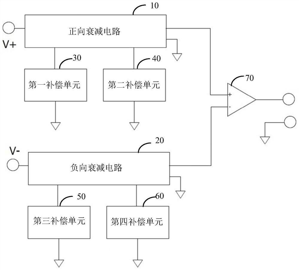
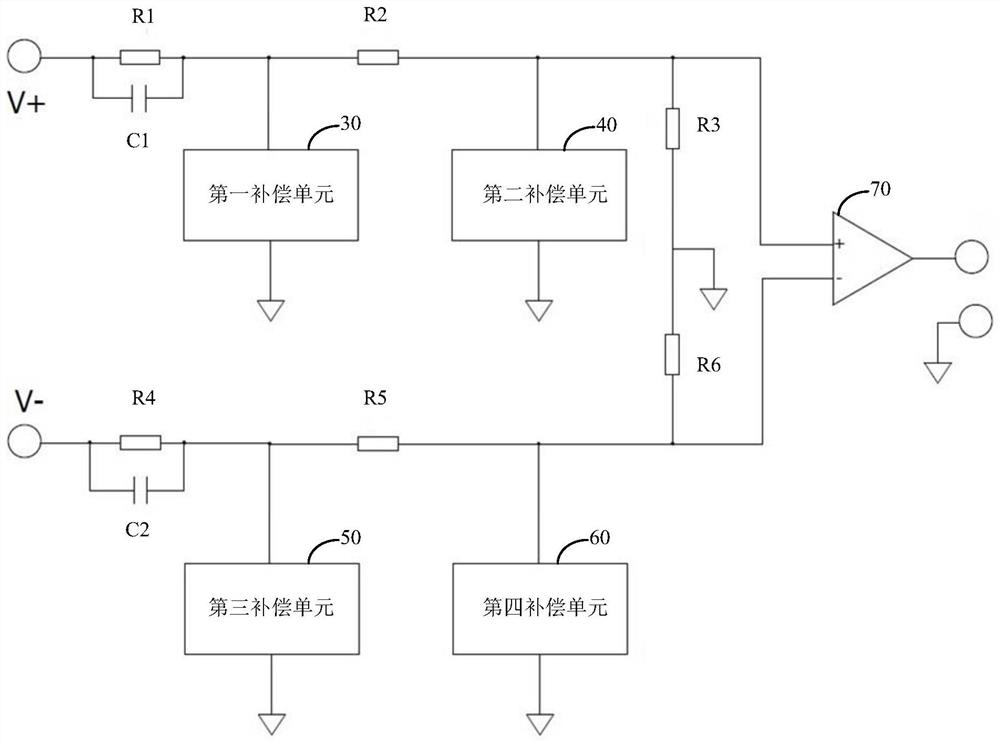
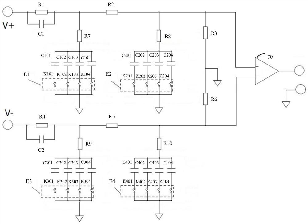
[0049] The present invention provides an attenuator, comprising a positive attenuation circuit and a negative attenuation circuit that are symmetrical to each other, a first compensation unit and a third compensation unit that are symmetrical to each other, a second compensation unit and a fourth compensation unit that are symmetrical to each other, and a differential amplifier ; The first compensation unit, the second compensation unit, the third compensation unit and the fourth compensation unit are all adjustable capacitance units composed of fixed-value capacitors; the forward signal to be measu...


PUM


Abstract

The invention provides an attenuator and a differential voltage probe. The attenuator comprises a positive attenuation circuit and a negative attenuation circuit which are mutually symmetrical, a first compensation unit and a third compensation unit which are mutually symmetrical, a second compensation unit and a fourth compensation unit which are mutually symmetrical, and a differential amplifier. The first compensation unit, the second compensation unit, the third compensation unit and the fourth compensation unit are all adjustable capacitor units composed of constant-value capacitors. A forward signal to be measured is attenuated through the forward attenuation circuit, and the frequency characteristic of a preset frequency point is adjusted through the first compensation unit and thesecond compensation unit. A negative signal to be measured is attenuated through the negative attenuation circuit, and the frequency characteristic of a preset frequency point is adjusted through thethird compensation unit and the fourth compensation unit. Finally, a difference value is calculated through the differential amplifier, the difference value is amplified and output. According to the invention, the problems of poor stability of the attenuator and distortion of the measurement result of the differential voltage probe in the prior art are effectively solved.

Description

technical field [0001] The invention relates to the field of electronic technology, in particular to an attenuator and a differential voltage probe. Background technique [0002] Differential voltage probe is a probe device used to measure high-voltage floating voltage, which is widely used in the field of power electronics. [0003] The high-voltage voltage to be measured of hundreds of volts is input from the positive and negative poles of the differential voltage probe, and then output after passing through the attenuator inside the differential voltage probe. In order to meet the frequency range of the signal to be tested, which can cover DC to 200M, the existing differential voltage probes are equipped with mutually symmetrical attenuators in the positive signal attenuation branch and the negative signal attenuation branch respectively, and the amplitude of the attenuator The frequency signature remains flat and symmetrical over a wide frequency range. The mutually sy...

Claims


Application Information

Patent Timeline
Patent Type & Authority Applications(China)
IPC IPC(8): G01R19/00G01R15/00H03H7/24
CPCG01R19/0084G01R15/00H03H7/24H03H7/25H03H2210/025H03H2210/036G01R19/10G01R1/30
Inventor 樊小明
Owner SHENZHEN ZHIYONG ELECTRONICS CO LTD
Why Eureka
Try Eureka