[0017] The present invention will be further described below in conjunction with the accompanying drawings:
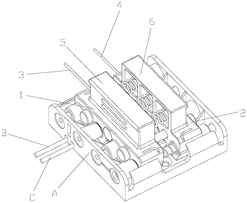
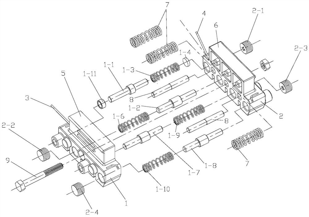
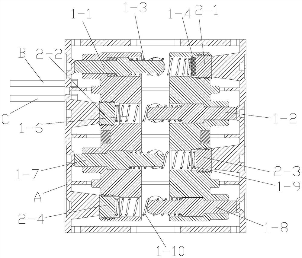
[0018] Referring to the accompanying drawings: the battery box rapid test device in this embodiment includes a positive electrode skeleton 1 and a negative electrode skeleton 2, the positive electrode skeleton 1 is connected with a positive input line 3, the negative electrode skeleton 2 is connected with a negative electrode input line 4, and the positive electrode skeleton 1 and the negative electrode skeleton 2 are provided with a set of positive conductive columns and a set of negative conductive columns. The positive conductive columns include a first positive conductive column 1-1 and a second positive conductive column 1-2. The negative conductive column includes a first negative conductive column. A column 2-1, a second negative electrode conductive column 2-2, one end of the first positive electrode conductive column 1-2 is mounted on the positive electrode frame 1, the other end is covered with a first spring 1-3, and one end of the first spring 1-3 is Covered on the first positive conductive column 1-1, the other end of the first spring 1-3 is connected with an insulating pad 1-4, one side of the insulating pad 1-4 is connected with the first spring 1-3, and the insulating pad 1- The other side of 4 is provided with a first negative electrode conductive column 2-1, the insulating pad 1-4 and the first negative electrode conductive column 2-1 are both arranged on the negative electrode frame 2, and the first positive electrode conductive column 1-1 is connected to the positive electrode input line. 3 connection, the first negative electrode conductive column 2-1 is connected to the negative electrode input line 4, one side of the first positive electrode conductive column 1-1 is provided with a second positive electrode conductive column 1-2, and one end of the second positive electrode conductive column 1-2 is Set on the negative skeleton 2, the other end of the second positive conductive column 1-2 is sheathed with a second spring 1-6, one end of the second spring 1-6 is sheathed on the second positive conductive column 1-2, and the second spring The other end of 1-6 is connected to the second negative electrode conductive column 2-2, and the second negative electrode conductive column 2-2 is arranged on the positive electrode frame 1.
[0019] The number of positive conductive columns is four, the number of negative conductive columns is four, the positive conductive column further includes a third positive conductive column 1-7, a fourth positive conductive column 1-8, and the negative conductive column also includes a third negative conductive column The column 2-3, the fourth negative electrode conductive column 2-4, the third positive electrode conductive column 1-7 are located on one side of the second positive electrode conductive column 1-5, and one end of the third positive electrode conductive column 1-7 is arranged on the positive electrode skeleton 1 On the other hand, a third spring 1-9 is sleeved on the other end of the third positive electrode conductive column 1-7, one end of the third spring 1-9 is sleeved on the third positive electrode conductive column 1-7, and the other end of the third spring 1-9 is sleeved on the third positive conductive column 1-7. One end is connected to the third negative electrode conductive column 2-3, the third negative electrode conductive column 2-3 is arranged on the negative electrode skeleton 2, one side of the third positive electrode conductive column 1-7 is provided with the fourth positive electrode conductive column 1-8, the fourth One end of the positive electrode conductive column 1-8 is set on the negative electrode frame 2, the other end of the fourth positive electrode conductive column 1-8 is covered with a fourth spring 1-10, and one end of the fourth spring 1-10 is covered with the fourth positive electrode conductive column. On 1-8, the other end of the fourth spring 1-10 is connected to the fourth negative electrode conductive column 2-4, and the fourth negative electrode conductive column 2-4 is arranged on the positive electrode frame 1.
[0020] The first positive electrode conductive column 1-1 is covered with a conductive sleeve 1-11, and the conductive sleeve 1-11 is connected to the positive electrode input line 3. As shown in FIG.
[0021] A handle part 1 5 is arranged on the positive electrode frame 1 , a handle part 2 6 is arranged on the negative electrode frame 2 , and a set of spring 2 7 is arranged between the handle part 1 5 and the handle part 2 6 .
[0022] A group of positioning posts 8 are arranged below the second spring 7 , and the positioning posts 8 are arranged between the positive electrode skeleton 1 and the negative electrode skeleton 2 .
[0023] A bolt 9 is connected between the positive electrode frame 1 and the negative electrode frame 2 .
[0024] The central protrusion of the positive conductive column divides the positive conductive column into two ends.
[0025] In the figure, the battery box is indicated as A, the positive output line is indicated as B, and the negative output line is indicated as C. Figure 4 , there are positive output and negative output according to the dotted line.
[0026] In the contacts of the battery box, the electrical connection is realized according to the negative output, and the electrical connection is realized according to the positive output. The number of positive conductive columns and negative conductive columns is a multiple of two, not limited to four. The capacity of the box varies.
[0027]The first positive conductive column 1-1, the second positive conductive column 1-2, the first spring 1-3, the second spring 1-6, the third positive conductive column 1-7, the fourth positive conductive column 1-8, The third spring 1-9, the fourth spring 1-10, the conductive sleeve 1-11, the first negative electrode conductive column 2-1, the second negative electrode conductive column 2-2, the third negative electrode conductive column 2-3, the fourth negative electrode The conductive pillars 2-4 and the spring 2 7 are all made of conductive materials, such as copper materials, iron materials, and the like.
[0028] When working, the battery box has been electrically connected to the electronic lock. First compress the positive skeleton 1 and the negative skeleton 2, and then compress the first spring 1-3, the second spring 1-6, the third spring 1-9, and the fourth spring 1. Under the compression action of -10 and spring 2 7, the distance between the positive electrode skeleton 1 and the negative electrode skeleton 2 shrinks, and the overall reduction is reduced. Negative skeleton 2, under the action of the first spring 1-3, the second spring 1-6, the third spring 1-9, the fourth spring 1-10 and the spring two 7, the distance is opened, the positive skeleton 1 and the negative skeleton 2 Tensioned in the battery box, then the first positive conductive column 1-1, the second positive conductive column 1-2, the third positive conductive column 1-7, and the fourth positive conductive column 1-8 are connected to the positive contact of the battery box. On the point, the first negative electrode conductive column 2-1, the second negative electrode conductive column 2-2, the third negative electrode conductive column 2-3, and the fourth negative electrode conductive column 2-4 are connected to the negative electrode contacts of the battery case, and then the positive electrode The input line and the negative input line are energized. Under the action of the insulating pad, the positive output is realized through the positive input line 3 and the first positive conductive column 1-1, and the negative input line 4, the first negative conductive column 2-1, The fourth positive conductive column 1-8, the fourth negative conductive column 2-4, the third positive conductive column 1-7, the third negative conductive column 2-3, the second positive conductive column 1-2, the second negative conductive column 2-2 Realize the negative output. When the battery box contacts are qualified and normal, the electronic lock will start normally. When the battery box contacts are unqualified, the electronic lock cannot be started to realize the detection process.
[0029] The characteristics of the embodiment of the present invention are: changing the previous inspection and testing mode that the battery box of the electronic lock needs to place batteries one by one, simulating the battery to detect the pass rate of the battery box of the electronic lock, and the detection of each contact of the battery box is completed at the same time , the detection efficiency has been greatly improved, the detection efficiency is high, the production efficiency of the electronic lock is improved, the labor cost is reduced, the detection can be carried out without the use of batteries, the production cost is reduced, and the detection of the battery box of the electronic lock is carried out effectively and quickly. process, the use effect is good, and it is conducive to promotion.
[0030] Although the present invention has been illustrated and described with reference to preferred embodiments, it will be understood by those of ordinary skill in the art that various changes in form and detail may be made within the scope of the claims.