
System and method for supplying power to vehicle-mounted electric appliance when fuel vehicle is parked

A technology for on-board electrical appliances and battery management systems, applied in the field of power supply for on-board electrical appliances of fuel vehicles, can solve the problems of large self-consumption, low power storage, and large pollution emissions of lead-acid batteries, achieve high fuel utilization efficiency, and prevent over-discharge damage , reduce the effect of lithium analysis

Active Publication Date: 2020-11-20
武汉极能新能源科技有限公司
View PDF7 Cites 0 Cited by
  • Summary
  • Abstract
  • Description
  • Claims
  • Application Information

AI Technical Summary

Problems solved by technology

[0005] At present, there are two ways to supply power to the parking on-board electrical appliances without starting the engine when the fuel vehicle is parked: one way is to install a micro fuel generator set on the vehicle to supply power. This method is suspected of illegal modification, low fuel efficiency, and loud running noise. , large pollution emissions, and considerable safety hazards; another way is to supply power from vehicle lead-acid batteries, but lead-acid batteries have defects such as large self-consumption, low discharge efficiency, less power storage, and short service life.

Method used


Image

  • System and method for supplying power to vehicle-mounted electric appliance when fuel vehicle is parked
  • System and method for supplying power to vehicle-mounted electric appliance when fuel vehicle is parked
  • System and method for supplying power to vehicle-mounted electric appliance when fuel vehicle is parked

Examples


Embodiment Construction

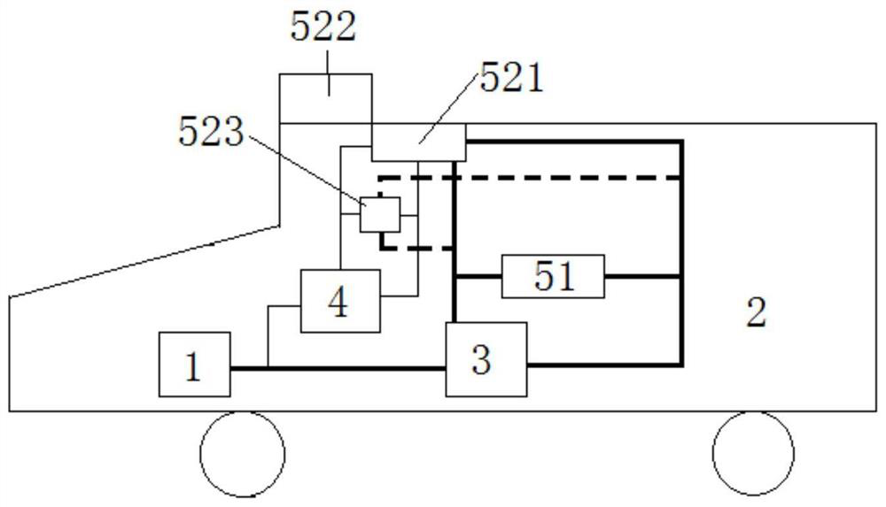
[0033] In order to make the object, technical solution and advantages of the present invention clearer, the present invention will be further described in detail below in conjunction with the accompanying drawings and embodiments. It should be understood that the specific embodiments described here are only used to explain the present invention, not to limit the present invention. In addition, the technical features involved in the various embodiments of the present invention described below can be combined with each other as long as they do not constitute a conflict with each other. In this paper, for the convenience of description, the vehicle-mounted electrical appliances that can be used when parking are defined as parking vehicle-mounted electrical appliances, and the vehicle-mounted electrical appliances that can be used when driving are defined as vehicle-mounted electrical appliances. The vehicle-mounted electrical appliances may or may not include parking vehicle-mount...


PUM


Abstract

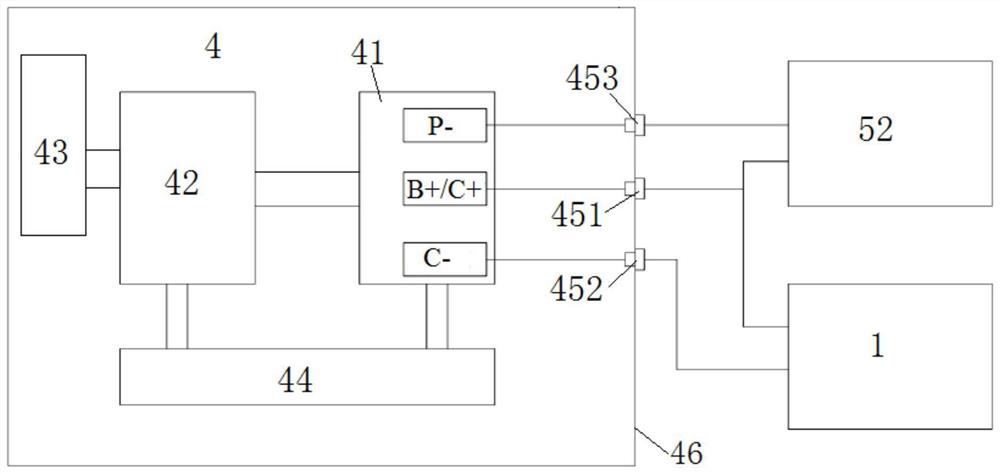
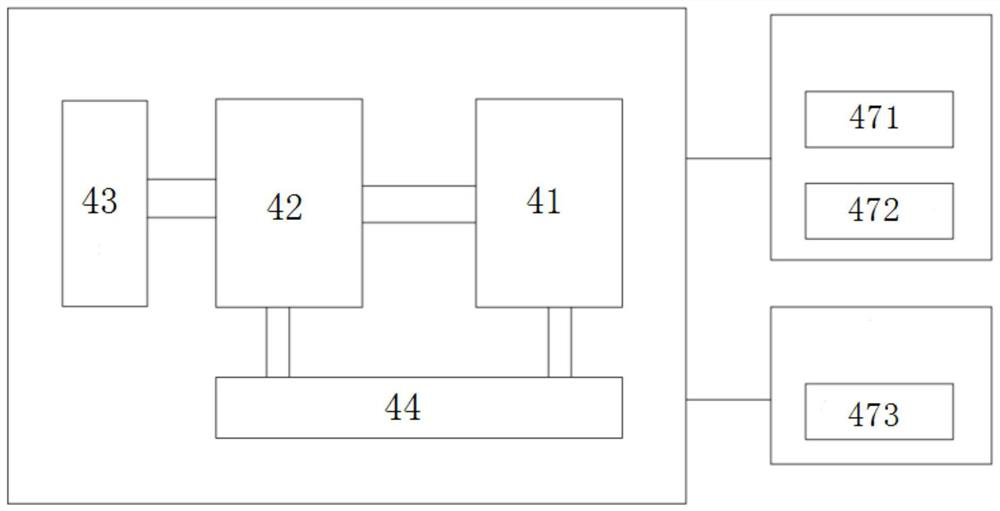
The invention discloses a system and a method for supplying power to a vehicle-mounted electric appliance when a fuel vehicle is parked. The system comprises a vehicle power generator, a vehicle lead-acid storage battery and a lithium battery system additionally arranged on a fuel vehicle, wherein the vehicle lead-acid storage battery and the lithium battery system are connected in parallel and then connected with the vehicle power generator to form a charging loop, the vehicle lead-acid storage battery is connected with each vehicle-mounted electric appliance to form a power supply loop, thelithium battery system is connected with each parking vehicle-mounted electric appliance to form a discharging loop, the lithium battery system comprises a lithium ion battery module, a high-voltage component, a box body, a battery management system protection plate with a charging current-limiting circuit and a power supply voltage detection circuit, a temperature sensor and a heating assembly, the lithium ion battery module, the high-voltage component and the battery management system protection plate are connected in sequence, the charging current-limiting circuit is serially connected between the vehicle power generator and the lithium battery system, and the power supply voltage detection circuit is serially connected to the discharging loop. According to the invention, the system islow in use cost, safe, long in service life, environmentally friendly and capable of effectively and stably operating for a long time.

Description

technical field [0001] The invention belongs to the technical field of power supply for on-board electrical appliances of fuel vehicles, and more particularly relates to a system and method for supplying power to on-board electrical appliances of fuel vehicles when they are parked. Background technique [0002] With the rapid development of science and technology, people have higher and higher requirements for the comfort of vehicles. When vehicles such as fuel trucks and RVs are parked, sometimes it is necessary to turn on the air conditioner, audio player, charger, refrigerator, kitchen Wei and other car electrical appliances. [0003] In the past, when the fuel vehicle used the original car air conditioner or used the on-board electrical appliances for a long time, it was necessary to turn on the vehicle at idle speed to drive the compressor or charge the lead-acid battery. There are many problems with vehicles idling for a long time. One is that it affects the life of t...

Claims


Application Information

Patent Timeline
Patent Type & Authority Applications(China)
IPC IPC(8): H02J7/00B60R16/033H01M10/0525H01M10/42H01M10/46H01M10/48H01M10/615H01M10/625
CPCH02J7/00712H02J7/007194H02J7/00304B60R16/033H01M10/0525H01M10/4207H01M10/425H01M10/46H01M10/482H01M10/486H01M10/488H01M10/615H01M10/625H01M2010/4271H01M2010/4278Y02E60/10
Inventor 胡皓东孙巍
Owner 武汉极能新能源科技有限公司
Learn More