Electrical cabinet drying device
A drying device and electrical cabinet technology, applied in the field of electrical cabinets, can solve the problems of occupying the use space of the electrical cabinet, increasing the internal temperature of the electrical cabinet, and the impact of use, and achieving the effects of improving the reliability of use, reducing manual operations, and improving practicability
- Summary
- Abstract
- Description
- Claims
- Application Information
AI Technical Summary
Problems solved by technology
Method used
Image

Examples
Embodiment
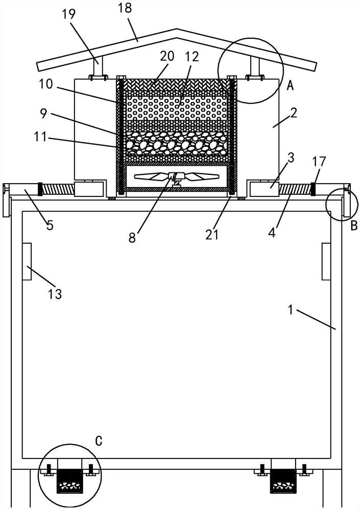
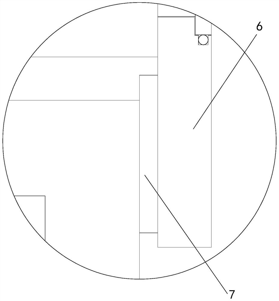
[0028] see Figure 1-5 , an electric cabinet drying device, comprising a cabinet body 1, and also includes a drying pipe 2, the four corners of the bottom of the drying pipe 2 are provided with rotating slots, and each rotating slot is provided with a rotating block 3 inside, rotating The top of the block 3 is connected with the inner wall of the top of the rotating groove through a rotating shaft, and the end of the rotating block 3 facing the outside of the rotating groove is connected with a threaded rod 4, and the outer threaded sleeve of the threaded rod 4 is provided with a threaded pipe 5, and the threaded pipe 5 The other end is rotatably connected with a splint 6, and the lower side of the splint 6 extends downwards. A rubber plate 7 is pasted on the inner wall of the splint 6, and the friction of the splint 6 is enhanced by the rubber plate 7. The inside of the drying pipe 2 is from bottom to top. Blower fan 8, the first net cage 9 and the second net cage 10 are inst...
PUM
 Abstract
Description
Claims
Application Information