Crystal rod cutting device and crystal rod cutting method

A cutting device and crystal rod technology, which is applied to fine working devices, working accessories, manufacturing tools, etc., can solve the problems of cutting line vibration and uneven surface of silicon wafers, and achieve the effect of avoiding uneven cutting surfaces.

Active Publication Date: 2022-05-31
XIAN ESWIN MATERIAL TECH CO LTD +1
View PDF0 Cites 0 Cited by
  • Summary
  • Abstract
  • Description
  • Claims
  • Application Information

AI Technical Summary

Problems solved by technology

[0004] In view of this, the present invention provides a crystal rod cutting device and a crystal rod cutting method, which can solve the problem in the prior art that the cutting line vibrates due to the spraying of mortar onto the cutting line, which in turn leads to the uneven surface of the cut silicon wafer

Method used


Image

  • Crystal rod cutting device and crystal rod cutting method
  • Crystal rod cutting device and crystal rod cutting method
  • Crystal rod cutting device and crystal rod cutting method

Examples


Embodiment Construction

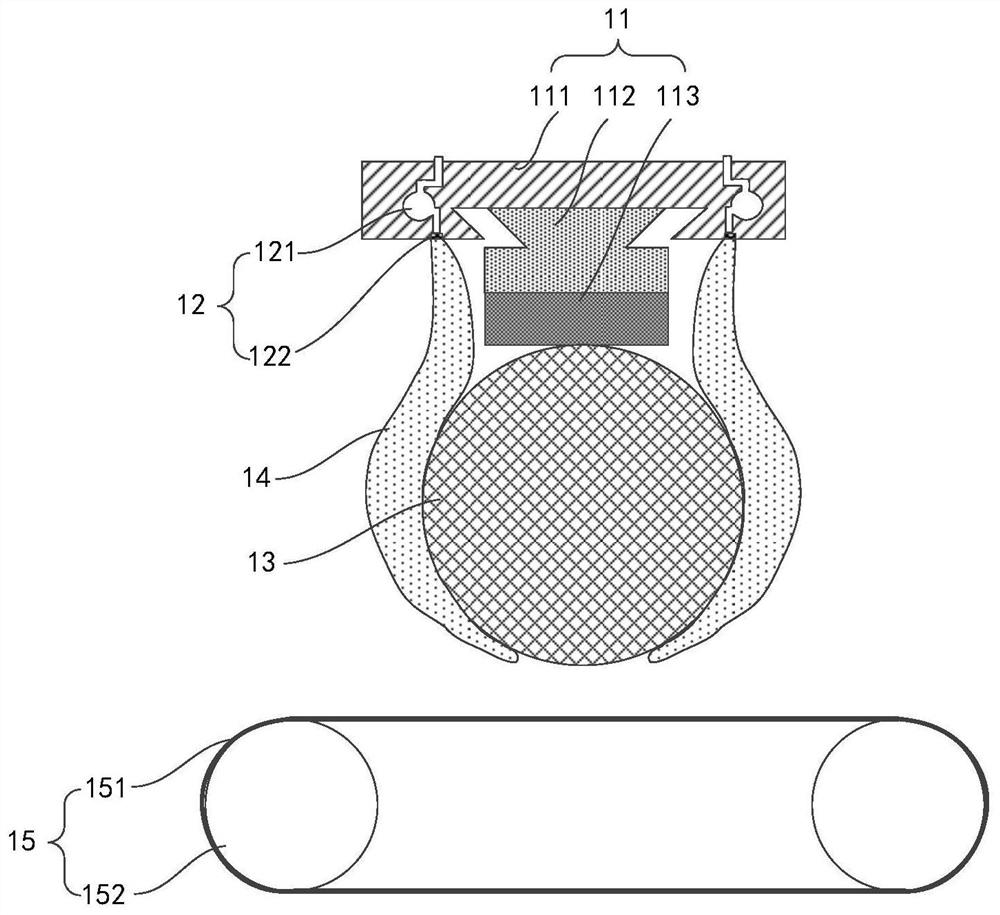
[0029] Thus, please refer to FIG. 1, which is a schematic structural diagram of a crystal rod cutting device provided by an embodiment of the present invention. Figure 1

[0031] Please continue to refer to FIG. 1, the feeding table 11 may specifically include an undercut wedge joint 111, a material table 112 and a support plate 113,

[0032] In the embodiment of the present invention, the mortar supply unit 12 may include a mortar supply pipe 121 and a mortar discharge port 122, which

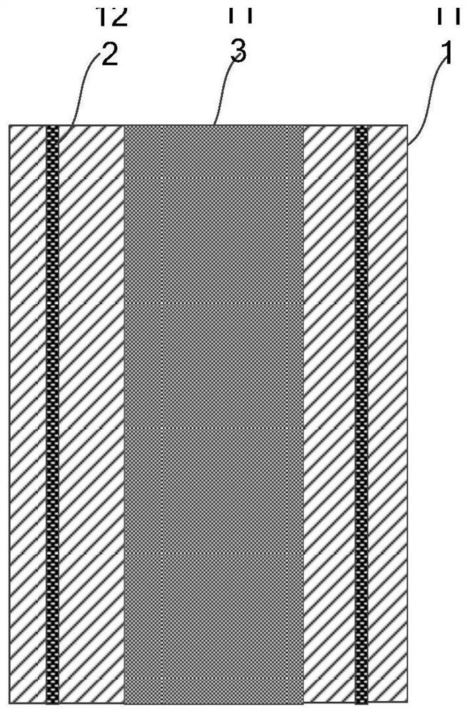
[0033] Please refer to FIG. 2, which is a schematic diagram of a mortar outlet provided in an embodiment of the present invention. As shown in Figure 2, the present invention is implemented

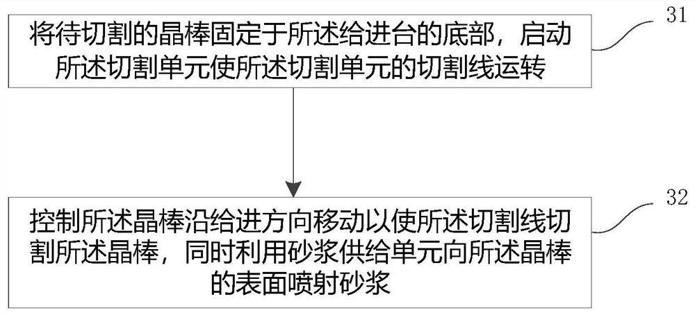
[0037] Please refer to FIG. 3, which is a schematic flowchart of a method for cutting an ingot according to an embodiment of the present invention. As shown in Figure 3,

[0043] According to the cutting speed, the mortar supply speed of the mortar supply unit is controlled to control the surface temperatur...


PUM


Abstract

The invention provides a crystal ingot cutting device and a crystal ingot cutting method. The crystal ingot cutting device comprises: a feeding table, the feeding table is used to fix the crystal ingot to be cut and drive the crystal ingot to be cut along the feeding A mortar supply unit, the mortar discharge ports of the mortar supply unit are located on both sides of the feeding table, and are used for spraying mortar on the surface of the ingot to be cut. According to the crystal ingot cutting device of the embodiment of the present invention, the mortar for wire cutting can be directly sprayed on the surface of the crystal ingot instead of the cutting line, thereby avoiding the impact of the cutting line caused by the mortar with a certain impulse being directly sprayed on the cutting line. Vibration occurs, which in turn avoids the occurrence of uneven cutting surfaces caused by the vibrating cutting line.

Description

A crystal rod cutting device and crystal rod cutting method technical field [0001] The present invention relates to the technical field of silicon wafer preparation, in particular to a crystal rod cutting device and a crystal rod cutting method. Background technique At present, in the wire cutting process of the ingot, the supplied mortar is usually sprayed onto the cutting wire with a certain pressure, and then The cutting line is attached with mortar to cut the crystal rod. On the one hand, the mortar can lubricate and clean the debris generated by cutting. On the other hand, the heat generated by cutting can be taken away. The quality of the wire cutting process determines the flatness of the surface of the silicon wafer obtained by cutting, if the surface of the silicon wafer is uneven, Subsequent additional trimming steps are required to correct excessively warped silicon wafers, which undoubtedly greatly increases the cost of silicon wafer preparation. costs ...

Claims


Application Information

Patent Timeline
Patent Type & Authority Patents(China)
IPC IPC(8): B28D5/04B28D7/00
CPCB28D5/045B28D5/007Y02P40/57
Inventor 姜镕
Owner XIAN ESWIN MATERIAL TECH CO LTD
Why Eureka
Try Eureka