
Steel wire continuous tempering electric heating furnace

A heating furnace and thermal power technology, applied in the direction of heat treatment furnaces, furnaces, furnace types, etc., can solve the problems of heat loss, increased workload, poor tempering temperature uniformity, etc., and achieve reduced workload, strong practicability, and compact structure Effect

Inactive Publication Date: 2020-11-24
山东国炬炉业有限公司
View PDF5 Cites 4 Cited by
  • Summary
  • Abstract
  • Description
  • Claims
  • Application Information

AI Technical Summary

Problems solved by technology

[0003] And the steel wire will bring in some miscellaneous slag after the previous process, but most of the existing steel wire tempering electric heating furnaces are not equipped with miscellaneous slag cleaning devices, resulting in the miscellaneous slag being brought into the interior of the steel wire tempering electric heating furnace during use. As a result, when the steel wire is tempered, it is necessary to open the steel wire tempering electric heating furnace and then clean up the slag inside it, which not only increases the workload, but also frequently opens the steel wire tempering electric heating furnace to easily cause heat loss. In addition, the existing When the steel wire tempering electric heating furnace is in use, its interior is only heated by the electric heating wire, and the tempering temperature uniformity is poor.

Method used


Image

  • Steel wire continuous tempering electric heating furnace
  • Steel wire continuous tempering electric heating furnace
  • Steel wire continuous tempering electric heating furnace

Examples


Embodiment

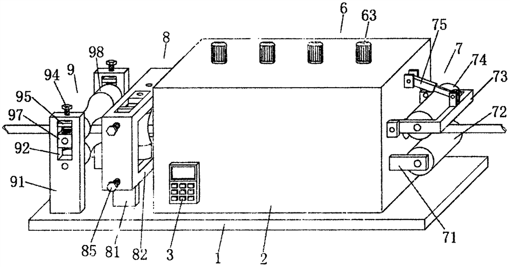
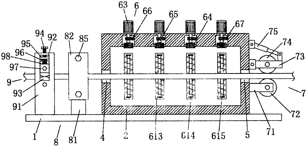
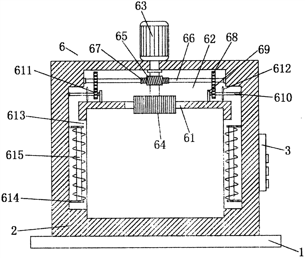
[0026] The steel wire continuous tempering electric heating furnace includes a bottom plate 1, a furnace body 2, a control panel 3, a material inlet 4, a material outlet 5, a tempering mechanism 6, a limit mechanism 7, a longitudinal cleaning mechanism 8 and a horizontal cleaning mechanism 9. One end of the top of the bottom plate 1 is fixedly connected with a furnace body 2, a control panel 3 is fixedly installed on one side of the furnace body 2, and a feed inlet 4 is provided on the side adjacent to the control panel 3 on the outside of the furnace body 2 , the side of the furnace body 2 away from the feed port 4 is provided with a discharge port 5, the steel wire enters the inside of the furnace body 2 through the feed port 4, and then stretches out through the discharge port 5; the inside of the furnace body 2 A tempering mechanism 6 is provided, a limiting mechanism 7 is provided on the outside of the furnace body 2 and outside the discharge port 5, and a longitudinal cle...


PUM


Abstract

The invention discloses a steel wire continuous tempering electric heating furnace. The steel wire continuous tempering electric heating furnace comprises a bottom plate, a furnace body, a control panel, a feed port, a discharge port, a tempering mechanism, a limiting mechanism, a longitudinal cleaning mechanism and a transverse cleaning mechanism, wherein the furnace body is fixedly connected toone end of the top of the bottom plate; the control panel is fixedly installed on one side of the furnace body; the feed port is formed in one side, adjacent to the control panel, of the outside of the furnace body; and the discharge port is formed in one side, away from the feed port, of the furnace body. The steel wire continuous tempering electric heating furnace is impact in structure, simpleand convenient to operate, high in practicability, and capable of cleaning steel wires with impurities in advance through the cooperation of the longitudinal cleaning mechanism and the transverse cleaning mechanism, so that the steel wires are prevented from bringing the impurities to the interior of the heating furnace, not only is the workload of operators reduced, but also the heat loss causedby frequent opening of the heating furnace is avoided; and in addition, through arranging the tempering mechanism in the furnace, hot air in the furnace can be circularly heated, so that the temperingand heating effect is greatly improved.

Description

technical field [0001] The invention belongs to the field of heating furnaces, in particular to a steel wire continuous tempering electric heating furnace. Background technique [0002] In existing life, steel wire is one of the four types of steel plates, tubes, shapes, and wires. It is a reprocessed product made of hot-rolled wire rods through cold drawing, and most steel wires need to be heated by tempering when processing. Furnace, steel wire tempering electric heating furnace is an important equipment for steel wire tempering after quenching. Its function is to make the quenched steel wire obtain good bending and torsion mechanical properties. [0003] The steel wire will bring in some slag after the previous process, but most of the existing steel wire tempering electric heating furnaces are not equipped with a slag cleaning device, resulting in the slag being brought into the interior of the steel wire tempering electric heating furnace during use. As a result, when ...

Claims


Application Information

Patent Timeline
Patent Type & Authority Applications(China)
IPC IPC(8): C21D9/56C21D1/18B24B27/033B24B27/00B24B5/38
CPCB24B5/38B24B27/0076B24B27/033C21D1/18C21D9/56C21D9/562
Inventor 王国庆
Owner 山东国炬炉业有限公司
Learn More