Demolition construction method for bridge superstructure

A construction method and bridge technology, applied in bridges, bridge maintenance, bridge reinforcement, etc., can solve the problems of imprecise hoisting arrangement and safety considerations, difficult implementation of mechanical equipment, insufficient bridge protection, etc., so as to be easy to grasp and implement, Demolition safety, good safety effect

Inactive Publication Date: 2020-11-24
武汉比邻工程技术有限公司
View PDF7 Cites 2 Cited by
  • Summary
  • Abstract
  • Description
  • Claims
  • Application Information

AI Technical Summary

Problems solved by technology

However, this demolition method mainly has the following problems: (1) It requires a better construction environment, and the construction boundary is limited (dense water network along the project, many farmlands, elevated lines with complex environment, etc.), incomplete mechanical equipment, and insufficient construction conditions (2) The layout of hoisting and safety considerations are not meticulous, which may easily cause waste of construction capacity; the protection of the part of the bridge that needs to be preserved is insufficient

Method used


Image

  • Demolition construction method for bridge superstructure
  • Demolition construction method for bridge superstructure
  • Demolition construction method for bridge superstructure

Examples


Embodiment 1

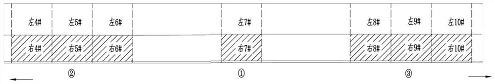
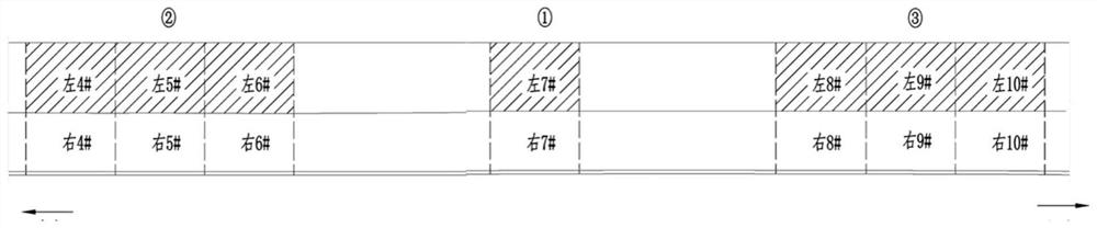
[0035] In order to facilitate understanding and description of the technical solution of the present invention, a certain section of bridge is selected as an example to describe in practice. The bridge has a total length of 417m. Ordinary concrete cast-in-place T beams, 25m prefabricated prestressed T beams, 15 holes in total; the demolition work is carried out in two stages: the first stage is to demolish the right (single) bridge deck and 28 pieces of T beams (including the main span of 25m fully hung Beams, semi-hanging beams and ordinary 25m prestressed T-beams); in the second stage, the left (single) bridge deck and 28 T-beams will be demolished. The demolition diagram is as follows figure 1 and figure 2 shown.

[0036] Only 4 T-beams need to be removed # 、5 # 、6 # 、7 # ,8 # ,9 # 、10 # A total of seven spans ( figure 1 and figure 2 The shaded part shown in ), combined with the actual situation on site, divided into three areas for demolition.

[0037] ①The No...

Embodiment 2

[0061] This embodiment provides the method for dismantling and hoisting safety calculation in Embodiment 1.

[0062] (1) Calculation of the weight of the removed beam

[0063] The concrete quantity of a main girder is shown in Table 1, and the self-weight Q of the most unfavorable middle girder (difficult) is taken 1 = 50.02t.

[0064] Table 1: Concrete Quantity Table for a Main Girder

[0065]

[0066] The average thickness of bridge deck pavement is 13cm, and the self-weight Q is calculated 2 =0.13×25×2.3×2.5=18.7t.

[0067] The number of prestressed steel tendons in a T-beam is shown in Table 2, and the total weight of prestressed steel tendons Q 3 = 0.57t.

[0068] Table 2: Quantity of Prestressed Tendon Materials for a T-beam

[0069]

[0070] Therefore, the hoisting weight of a center beam Q=Q1+Q2+Q3=50.02+19.07+0.57=69.66t, rounded to 70t.

[0071] (2) Selection of hoisting machinery and spreaders

[0072] According to the above calculation results, projec...


PUM


Abstract

The invention discloses a demolition construction method for a bridge superstructure. The demolition construction method mainly comprises the steps of demolition preparation, construction safety enclosure, demolition of a bridge deck crash barrier, demolition of a bridge deck, demolition of a beam plate and site clearing, wherein the demolition of the beam plate comprises main span full-suspendedbeam demolition operation and semi-suspended beam and T beam demolition operation; and the main span full-suspended beam demolition operation and the semi-suspended beam and T beam demolition operation each comprise the steps of removing longitudinal and transverse connection, taking a beam, lowering the beam and transporting the beam. The demolition construction method is basically opposite to the installation process of a bridge, and is convenient to master and implement; and under the conditions that the construction boundary is limited and mechanical equipment and construction conditions do not exist, the construction method is adopted for solving the problem of integral demolition of a beam body, is small in operation influence, ensures the construction safety, and has certain popularization significance.

Description

technical field [0001] The invention relates to the technical field of bridge construction, in particular to a construction method for dismantling a bridge superstructure. Background technique [0002] As we all know, construction projects are based on reinforced concrete. In the process of engineering construction, due to changes or errors in design functions and problems in construction quality, some concrete structures that have been poured must be demolished. The traditional method is manual Chiseling or mechanical crushing, and more advanced ones are static crushing or blasting demolition, but these methods are either low in efficiency, high in risk, and generally cause serious noise and pollution, and these methods are harmful to qualified retained structures during the demolition process. Different degrees of disturbance damage will occur, resulting in cracks in the retained part of the concrete or separation of steel bars and concrete, making it difficult to meet the...

Claims


Application Information

Patent Timeline
Patent Type & Authority Applications(China)
IPC IPC(8): E01D24/00
CPCE01D22/00
Inventor 许国华沈华许嘉琦张源森刘立旋徐林吴刚
Owner 武汉比邻工程技术有限公司
Why Eureka
Try Eureka