Pulse fatigue test device for pressure vessel

A pressure vessel and fatigue test technology, which is applied in fluid pressure actuation device, fluid pressure actuation system test, application of repeated force/pulsation force to test material strength, etc. It can solve the deviation of fatigue test results and the inability to monitor hydraulic oil tank in real time Gas pressure and other issues to achieve the effect of reducing noise, saving labor costs, and improving the working environment

Pending Publication Date: 2020-11-24
ZOOMLION HEAVY IND CO LTD
View PDF13 Cites 0 Cited by
  • Summary
  • Abstract
  • Description
  • Claims
  • Application Information

AI Technical Summary

Problems solved by technology

However, since the actual working conditions of the hydraulic oil tank are not simulated, the fatigue test process is somewhat different from the actual working conditions, resulting in a certain deviati

Method used


Image

  • Pulse fatigue test device for pressure vessel
  • Pulse fatigue test device for pressure vessel
  • Pulse fatigue test device for pressure vessel

Examples


Embodiment Construction

[0044] Specific embodiments of the present invention will be described in detail below in conjunction with the accompanying drawings. It should be understood that the specific embodiments described here are only used to illustrate and explain the present invention, and are not intended to limit the present invention.

[0045] In addition, the terms "first", "second", "third" and "fourth" are used for descriptive purposes only, and should not be understood as indicating or implying relative importance or implying the number of indicated technical features Therefore, features defined as "first", "second", "third" and "fourth" may explicitly or implicitly include one or more of said features.

[0046] In the description of the present invention, it should be noted that unless otherwise specified and limited, the terms "setting" and "connection" should be understood in a broad sense, for example, it can be a fixed connection, a detachable connection, or a Integral connection; it ...


PUM


Abstract

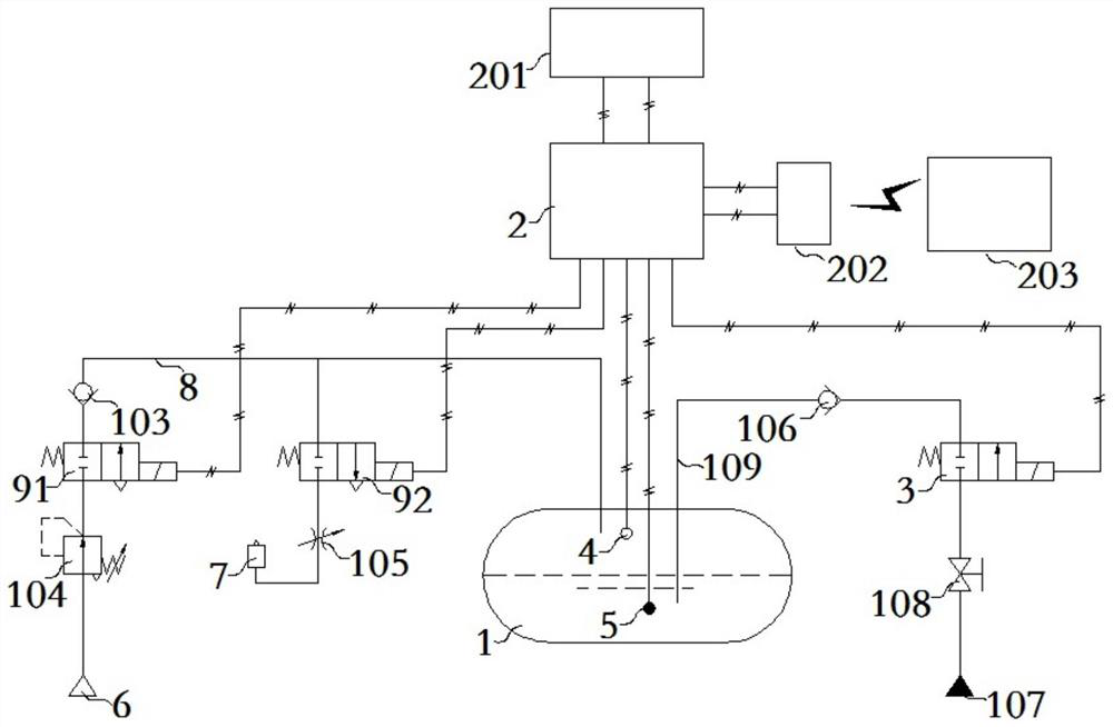
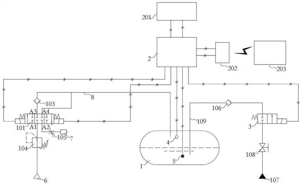
The invention relates to fatigue test equipment. The invention discloses a pulse fatigue test device for a pressure vessel. The device comprises a pneumatic loop and a hydraulic loop which are respectively connected with a test container (1). A pneumatic control device is arranged on the pneumatic loop. The air pressure in the test container (1) can be controlled through the pneumatic control device. A hydraulic control device (3) is arranged on the hydraulic loop so that the liquid level in the test container (1) can be controlled through the hydraulic control device (3), and an air pressuredetection unit (4) used for detecting air pressure and a liquid level detection unit (5) used for detecting the liquid level are arranged in the test container (1). According to the invention, the actual working condition of the pressure vessel can be better simulated, so that the result of the fatigue test is more accurate.

Description

technical field [0001] The invention relates to fatigue test equipment, in particular to a pressure vessel pulse fatigue test device. Background technique [0002] Pressure vessels such as hydraulic oil tanks and diesel tanks are widely used in construction machinery and are important components for storing oil. They are mainly made of steel and have many welds. In the actual work of the fuel tank, due to the difference in the flow rate of the oil inlet / return oil and the temperature change in the oil work, the oil tank has expansion and contraction deformation. Due to the long-term repeated changes, the fatigue of the weld seam of the fuel tank is caused. . In the use of fuel tanks of construction machinery, there are often cracks in the fuel tank caused by long-term shrinkage and expansion deformation, which leads to the failure of the whole machine to work; in order to ensure the performance of the pressure vessel, various types of pressure vessels need to be fatigued t...

Claims


Application Information

Patent Timeline
IPC IPC(8): G01N3/36F15B19/00
CPCG01N3/36F15B19/007
Inventor 陈艳军吴元峰陈中赵均强
Owner ZOOMLION HEAVY IND CO LTD
Why Eureka
Try Eureka