Sewage analysis and assessment system for supervision

A sewage analysis and supervision technology, applied in the direction of analysis materials, test water, cleaning methods and utensils, etc., can solve the problem of low detection accuracy of sampled sewage

Active Publication Date: 2020-11-24
安徽恒信建设工程管理有限公司
7 Cites 0 Cited by

AI-Extracted Technical Summary

Problems solved by technology

[0005] In order to improve the problem of low detection accuracy of sampled sewage existing in rela...

Method used

With reference to Fig. 1 and Fig. 2, control module 2 is electrically connected with the raindrop sensor 25 that is used to detect whether it is raining near the sewage channel, when raindrop sensor 25 detects raining, it sends switch ...

Abstract

The invention relates to a sewage analysis and assessment system for supervision, and relates to the technical field of sewage detection. The system comprises a supporting frame and a sampling box, and a water outlet pipe and a locking valve penetrate through the bottom of the sampling box; a detection unit is arranged in the sampling box, the detection unit is electrically connected with a control module, and the control module is electrically connected with a wireless transmission module used for transmitting detection data to a mobile terminal or a computer terminal; a sewage pump is arranged on the side wall of the supporting frame, the inlet end of a sewage pump communicates with a sewage inlet pipe, and the outlet end of the sewage pump communicates with a sewage discharging pipe; aclear water tank is arranged on the side, close to the sewage pump, of the supporting frame, a clear water pipe is arranged at the lower end of the clear water tank, a butt-joint pipe is arranged at the end, away from the sewage pump, of the sewage inlet pipe, a three-way adjusting valve is arranged among the sewage inlet pipe, the butt-joint pipe and the clear water pipe, and the three-way adjusting valve and the sewage pump are electrically connected to the control module; the sewage analysis and assessment system has the effects that the sampling box is cleaned, and the influence of previous sewage impurities on the accuracy of subsequent sewage detection is reduced.

Application Domain

Preparing sample for investigationTesting water +1

Technology Topic

Water pipeWater tanks +7

Image

  • Sewage analysis and assessment system for supervision
  • Sewage analysis and assessment system for supervision
  • Sewage analysis and assessment system for supervision

Examples

  • Experimental program(1)

Example Embodiment

[0033] The following is attached Figure 1-3 Give further details on this application.
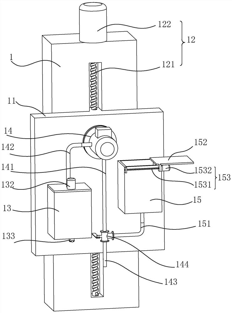
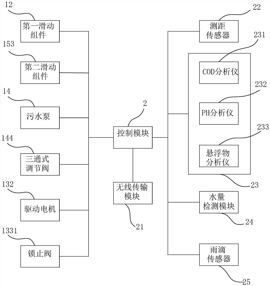
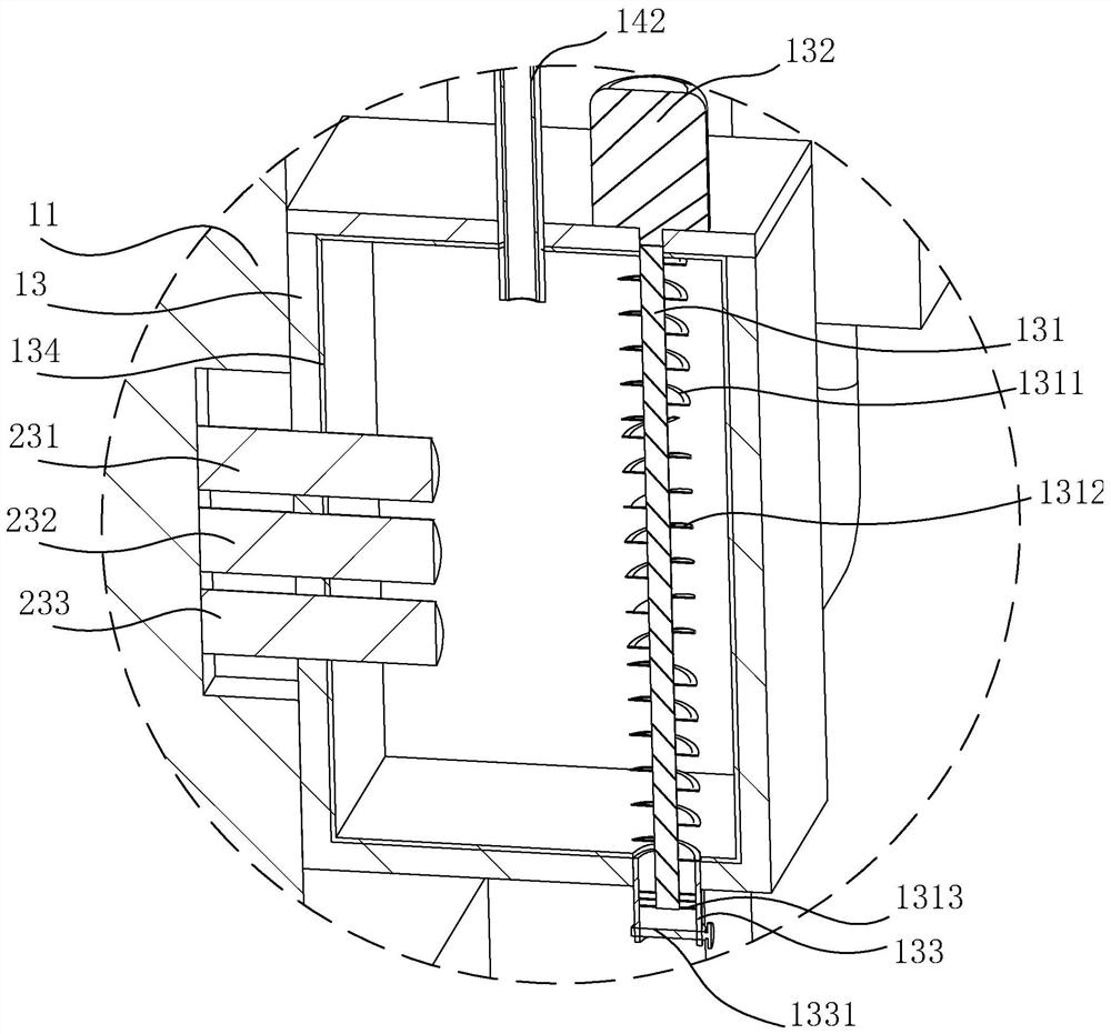
[0034] The embodiment of the application discloses a sewage analysis and assessment system for supervision. Reference figure 1 with figure 2 The sewage analysis and assessment system includes a sampling box 13 for collecting sewage and a sewage pump 14 for pumping sewage in the sewage channel to the sampling box 13. The sampling box 13 is fixedly installed with a detection unit 23 for detecting the quality of the sewage. The detection unit 23 includes a COD analyzer 231, a PH analyzer 232, and a suspended matter analyzer 233; the data output terminal of the detection unit 23 is electrically connected to a control module 2, which can be a PLC controller produced by Siemens; control module 2 The wireless transmission module 21 for remotely transmitting the detection data to the mobile terminal or the computer terminal is electrically connected. The wireless transmission module 21 may be a GPRS wireless transmission module 21.
[0035] Reference figure 1 , It also includes a support frame 1 vertically fixed in the sewage channel. The side wall of the support frame 1 is slidingly connected with a sliding plate 11 along its height direction. The sampling box 13 and the sewage pump 14 are both fixedly connected to the sliding plate 11 by bolts. On the side wall away from the support frame 1; the support frame 1 is provided with a first sliding assembly 12 for driving the sliding plate 11 to slide along the height direction of the support frame 1. The first sliding assembly 12 includes a first screw 121 and a The first motor 122 that drives the first screw 121 to rotate in the circumferential direction is electrically connected to the control module 2. The side wall of the sampling box 13 and the lower end of the sampling box 13 are fixedly installed with a ranging sensor 22 for detecting the height of the sewage liquid level. The distance measuring sensor 22 may be an ultrasonic distance measuring sensor 22; the distance measuring sensor 22 is electrically connected to the control module 2. When the distance between the distance measuring sensor 22 and the liquid surface is lower than the preset value, the control module 2 The first sliding assembly 12 drives the sliding plate 11 to move away from the sewage channel, so as to reduce the possibility that the lower end of the sampling box 13 is immersed in the sewage and is corroded by the sewage.
[0036] Reference figure 2 with image 3 The inlet end of the sewage pump 14 is connected with a sewage pipe 141 through a flange, and the outlet end of the sewage pump 14 is connected with a sewage pipe 142 through a flange. The end of the sewage pump 142 far away from the sewage pump 14 is located inside the sampling box 13. 14 is electrically connected to the control module 2 to control the start of the sewage pump 14 through the solenoid valve provided in the control module 2 and transport the sewage to the sampling box 13; the sewage inlet pipe 141, the sewage pipe 142 and the inner wall of the sampling box 13 are all fixedly bonded There is an anti-corrosion layer 134, and the anti-corrosion layer 134 may be epoxy paint to prevent harmful substances in the sewage from corroding the sewage pipe 141, the sewage pipe 142 and the inner wall of the sampling box 13.
[0037] Reference figure 2 with image 3 The lower end of the sampling box 13 is provided with a water outlet pipe 133 for discharging sewage. The side wall of the water outlet pipe 133 is provided with a lock valve 1331 for opening and closing the water pipe 133. The lock valve 1331 is an electric valve, and the lock valve 1331 is electrically connected to The control module 2 automatically starts the opening and closing of the water outlet pipe 133 through the control module 2; the sampling box 13 is provided with a spiral rod 131 along its height direction. The lower end of the spiral rod 131 is located in the water outlet pipe 133, and the outer wall of the spiral rod 131 is fixedly welded with The forward spiral piece 1311 and the reverse spiral piece 1312, the reverse spiral piece 1312 is located between the two sets of forward spiral pieces 1311; the upper surface of the sampling box 13 is fixedly installed with a drive motor 132 for driving the spiral rod 131 to rotate in the circumferential direction through bolts , The driving motor 132 is electrically connected to the control module 2; when the sewage in the sampling box 13 is discharged, the control module 2 activates the driving motor 132 to drive the screw rod 131 to rotate to accelerate the discharge of the sewage. Turning to the spiral blade 1311 is opposite, which is convenient for crushing the particulate matter in the sewage and preventing it from blocking the water outlet pipe 133.
[0038] Reference figure 2 with image 3 The outer wall of the spiral rod 131 near the outlet pipe 133 is fixedly bonded with a cleaning brush 1313 along its circumference. The sidewall of the cleaning brush 1313 away from the spiral rod 131 is attached to the inner wall of the outlet pipe 133. When the spiral rod When the 131 rotates, the cleaning brush 1313 scrapes the outlet pipe 133 to further reduce the possibility that impurities in the sewage block the outlet pipe 133.
[0039] Reference figure 1 with figure 2 The end of the liquid inlet pipe away from the sewage pump 14 is provided with a butt pipe 143. The side wall of the sliding plate 11 close to the sewage pump 14 is fixedly welded with a clean water tank 15. The clean water tank 15 contains a sewage pipe 141 for cleaning and sewage discharge. The clean water source of the pipe 142 and the sampling box 13; the lower end of the clean water tank 15 is inserted with a clean water pipe 151 for outputting clean water, and a three-way regulating valve 144 is commonly connected between the clean water pipe 151, the sewage inlet pipe 141 and the docking pipe 143. The three-way regulating valve 144 is electrically connected to the control module 2; when the three-way regulating valve 144 is adjusted through the control module 2 to connect the sewage inlet pipe 141 with the docking pipe 143, it is in the sampling state, and the three-way regulation is adjusted through the control module 2. When the valve 144 connects the sewage inlet pipe 141 with the clean water pipe 151, clean water is drawn by the sewage pump 14 to clean the sewage inlet pipe 141, the sewage pipe 142 and the sampling box 13; then the three-way regulating valve 144 is adjusted to remove the clean water pipe 151. It communicates with the butt pipe 143 to realize the cleaning of the butt pipe 143.
[0040] Reference figure 2 with image 3 , The clean water tank 15 is provided with a water volume detection module 24 for detecting the water volume inside the clean water tank 15. The water volume detection module 24 may be a water level sensor, and the water volume detection module 24 is electrically connected to the control module 2; the clean water tank 15 is provided with a sealing cover 152 at the upper end, The side wall of the clean water tank 15 is provided with a second sliding assembly 153 for driving the sealing cover 152 to open or cover the clean water tank 15. The second sliding assembly 153 includes a second screw rod 1531 rotatably connected to one side of the clean water tank 15 and a For the second motor 1532 that drives the second screw 1531 to rotate in the circumferential direction, the second motor 1532 is electrically connected to the control module 2, and one side of the sealing cover 152 is integrally formed with a sliding block threaded on the outer side wall of the second screw 1531 1521: The water level sensor detects the remaining water volume inside the clean water tank 15. When the water volume is too low, the control module 2 uses the second sliding assembly 153 to open the sealing cover 152 for replenishing clean water.
[0041] Reference figure 1 with figure 2 The control module 2 is electrically connected with a raindrop sensor 25 for detecting whether it is raining near the sewage channel. When the raindrop sensor 25 detects rain, it sends a switch signal to the control module 2, and the control module 2 is opened by the second sliding assembly 153 The sealing cover 152 is supplemented by rainwater, which reduces the labor intensity of the operator to transfer the water source outside.
[0042] The implementation principle of the sewage analysis and assessment system for supervision in the embodiment of the application is: when sampling, the three-way regulating valve 144 is first adjusted through the control module 2 to make the sewage inlet pipe 141 communicate with the butt pipe 143, and then the sewage is started The pump 14 pumps the sewage into the sampling box 13, and then the detection unit 23 detects the PH value, COD amount and the suspended matter in the sewage, and transmits the detected data to the control module 2, which is wirelessly transmitted by the module 21. Remotely transmit the detection data to the mobile terminal or computer terminal, so as to realize the automatic detection of sewage water quality.
[0043] After the sampling test is completed, the lock valve 1331 is opened through the control module 2 and the drive motor 132 is activated, so that the screw rod 131 accelerates the discharge of the sewage in the process of discharging the sewage in the sampling box 13 to reduce the blockage of the outlet pipe 133; The control module 2 adjusts the three-way regulating valve 144, the sewage inlet pipe 141 is connected to the clean water pipe 151, and the butt pipe 143 is closed. At this time, the sewage pump 14 draws clean water to clean the sewage inlet pipe 141, the sewage pipe 142 and the sampling box 13. Reducing the impurities in the previously incompletely discharged sewage affects the detection accuracy of subsequent sampling sewage.
[0044] After the sampling box 13 is cleaned, close the lock valve 1331 and the drive motor 132, and then adjust the three-way regulating valve 144 again through the control module 2 so that the sewage pipe 141 is closed, and the butt pipe 143 is connected to the clean water pipe 151 to The clean water flows from the clean water pipe 151 into the butt pipe 143 and finally flows out of the butt pipe 143, so that the butt pipe 143 is cleaned, and the influence of impurities in the previously incompletely discharged sewage on the detection accuracy of subsequent sampling sewage is further reduced.
[0045] The above are the preferred embodiments of this application, and the scope of protection of this application is not limited accordingly. Therefore: all equivalent changes made in accordance with the structure, shape, and principle of this application shall be covered by the scope of protection of this application Inside.

PUM

no PUM

Description & Claims & Application Information

We can also present the details of the Description, Claims and Application information to help users get a comprehensive understanding of the technical details of the patent, such as background art, summary of invention, brief description of drawings, description of embodiments, and other original content. On the other hand, users can also determine the specific scope of protection of the technology through the list of claims; as well as understand the changes in the life cycle of the technology with the presentation of the patent timeline. Login to view more.
Why Eureka
Try Eureka