A laminated coil component

A coil component, laminated technology, applied to transformer/inductor parts, electrical components, transformer/inductor coils/windings/connections, etc., can solve the problems of installation and high frequency characteristics, insufficient characteristics, stray Capacitance and other problems, to achieve excellent results in mountability and high-frequency characteristics

Pending Publication Date: 2020-11-24
MURATA MFG CO LTD
View PDF8 Cites 0 Cited by
  • Summary
  • Abstract
  • Description
  • Claims
  • Application Information

AI Technical Summary

Problems solved by technology

However, in the laminated coil described in Patent Document 1, there is a concern that the characteristics in the high-frequency band of about 50 GHz may be insufficient.
In addition, if an external electrode is provided on the mounting surface side of the multilayer coil described in Patent Document 1, stray capacitance will be generated between the external electrode and the internal conductor, making it difficult to achieve both mountability and high-frequency characteristics. question

Method used


Image

  • A laminated coil component
  • A laminated coil component
  • A laminated coil component

Examples


Embodiment Construction

[0024] Hereinafter, the laminated coil component of the present invention will be described.

[0025] However, this invention is not limited to the following embodiment, It can change suitably and apply in the range which does not change the summary of this invention. In addition, it is also the invention that combines two or more of the respective preferred structures described below.

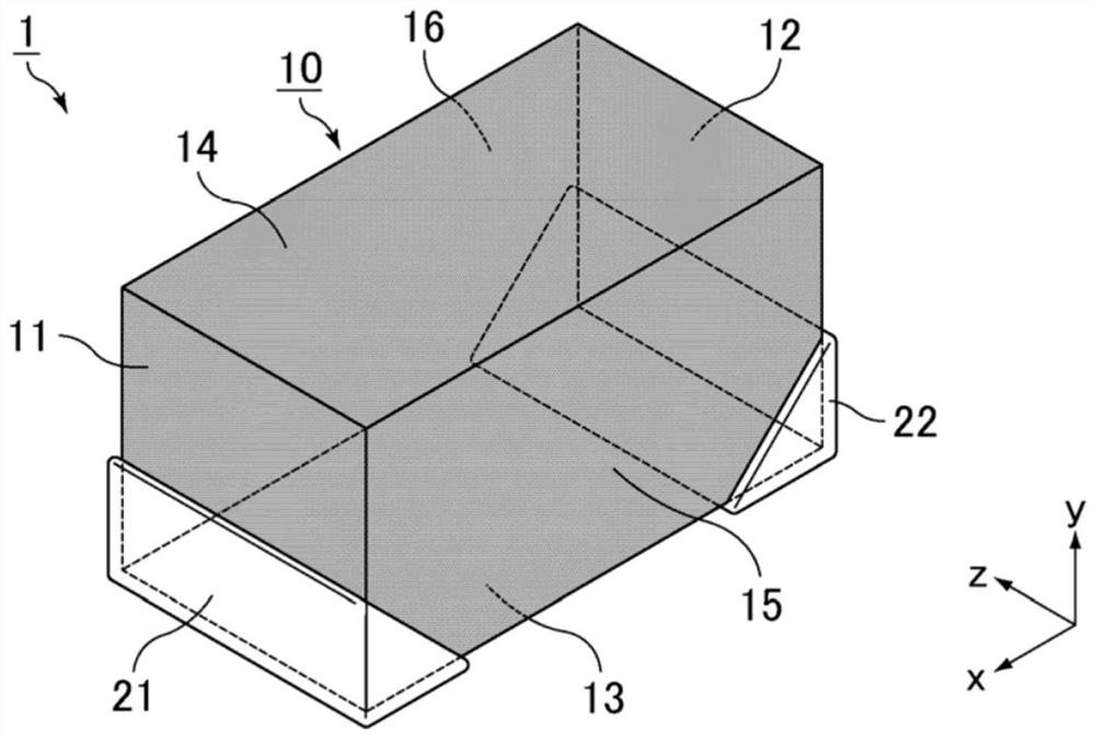
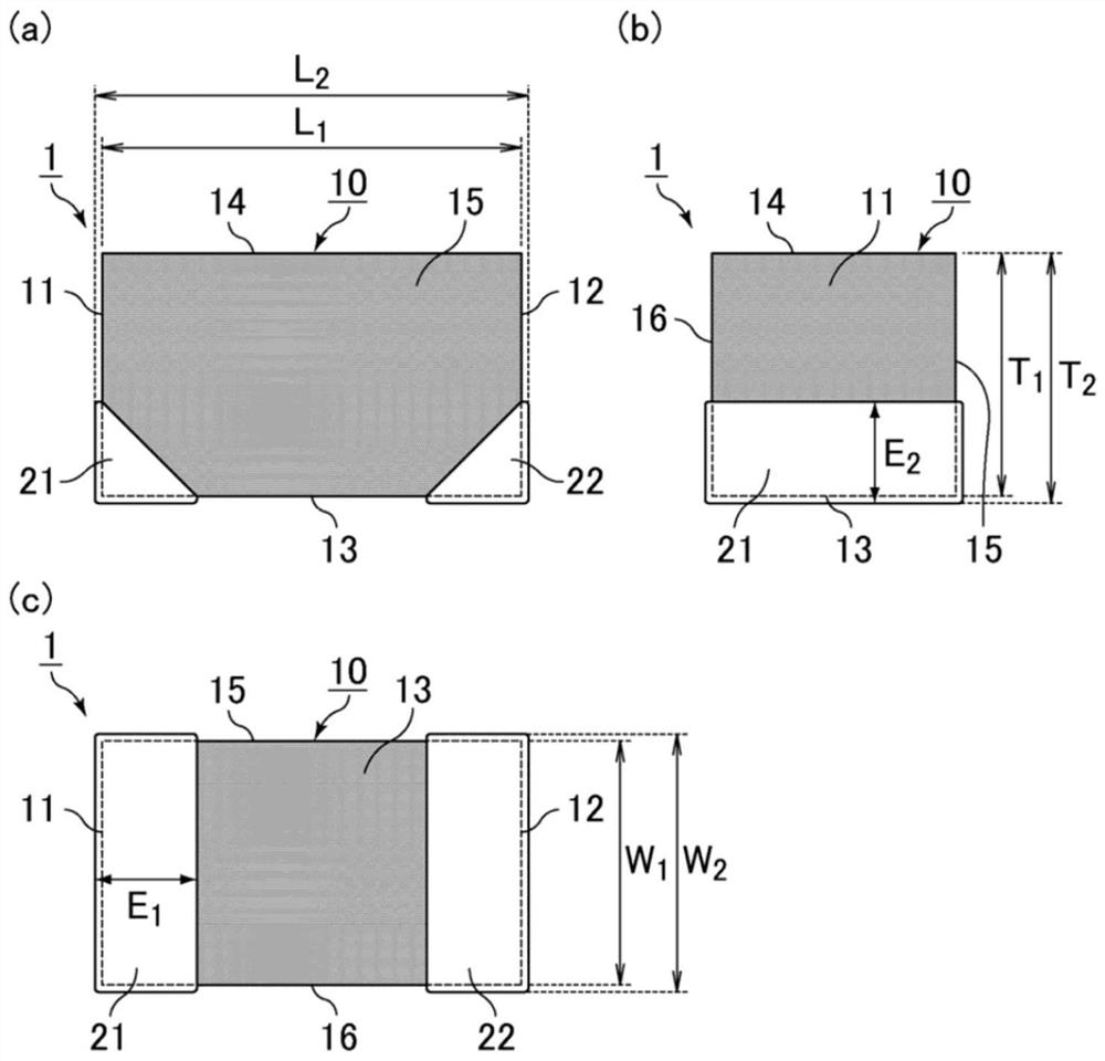
[0026] figure 1 It is a perspective view schematically showing an example of the laminated coil component of the present invention. figure 2 (a) is figure 1 A side view of the laminated coil assembly shown, figure 2 (b) is figure 1 The front view of the laminated coil part shown, figure 2 (c) is figure 1 Bottom view of the laminated coil component shown.

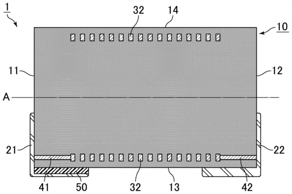
[0027] figure 1 , figure 2 of (a), figure 2 (b) of and figure 2 The laminated coil component 1 shown in (c) includes a laminated body 10 , a first external electrode 21 , and a second external electrode 22 . The laminated b...


PUM

PropertyMeasurementUnit
lengthaaaaaaaaaa
lengthaaaaaaaaaa
widthaaaaaaaaaa

Abstract

The present invention provides a laminated coil component having excellent mountability and high-frequency characteristics. The laminated coil component is provided with a laminated body, a first external electrode and a second external electrode. The coil is formed by electrically connecting a plurality of coil conductors stacked together with the insulating layer in the longitudinal direction. The laminated body has first and second end surfaces, first and second main surfaces, and first and second side surfaces. The first external electrode extends to cover at least a part of the first endsurface and a part of the first main surface. The second external electrode extends to cover at least a part of the second end surface and a part of the first main surface, a stacking direction of thelaminated body and a coil axial direction of the coil are parallel to the first main surface, and a low dielectric constant layer having a relative dielectric constant smaller than that of the insulating layer is provided between the laminated body and the first external electrode extending along the first main surface.

Description

technical field [0001] The present invention relates to a laminated coil component. Background technique [0002] As a laminated coil component, for example, Patent Document 1 discloses a laminated coil in which the lamination direction of insulating sheets and the coil axis are parallel to the mounting surface. [0003] Patent Document 1: Japanese Patent Application Laid-Open No. 09-129447 [0004] However, the multilayer coil described in Patent Document 1 has a problem of poor mountability because no external electrodes are provided on the mounting surface side, although stray capacitance can be suppressed. [0005] On the other hand, with the increase in communication speed and miniaturization of electrical machines and equipment in recent years, multilayer inductors are required to have sufficient high-frequency characteristics in a high-frequency band (for example, a GHz band of 50 GHz or higher). However, in the laminated coil described in Patent Document 1, there i...

Claims


Application Information

Patent Timeline
Patent Type & Authority Applications(China)
IPC IPC(8): H01F17/00H01F27/28H01F27/29H01F27/34
CPCH01F17/0013H01F27/2804H01F27/292H01F27/34H01F2017/002H01F2027/2809
Inventor 比留川敦夫
Owner MURATA MFG CO LTD
Why Eureka
Try Eureka