Water and fertilizer integrated precise irrigation system based on Internet intelligent control
An intelligent control and precision irrigation technology, applied in fertilization devices, watering devices, liquid fertilizer distribution, etc., can solve the problems of excessive chemical fertilization and irrigation, affecting production, high labor intensity, etc., to prevent irrigation effects and prevent liquid leakage , the effect of improving the accuracy
- Summary
- Abstract
- Description
- Claims
- Application Information
AI Technical Summary
Problems solved by technology
Method used
Image
Examples
Embodiment 1
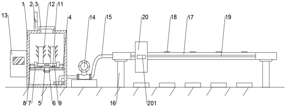
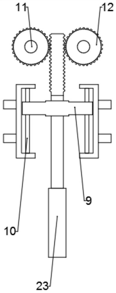
[0035] see Figure 1-5 , a water and fertilizer integrated precision irrigation system based on Internet intelligent control, including a housing 1, a controller 13, a water pump 14 and an electric rod 23, the upper surface of the housing 1 is provided with a water inlet 2 and a fertilizer inlet 3, and the water inlet 2 and The fertilizer port 3 is separated to facilitate the staff to put in the medium prepared in proportion. The housing 1 is provided with a fixed plate 4. The fixed plate 4 is provided with an opening 5. The opening 5 is provided with a solenoid valve 6. The solenoid valve 6 controls the inside of the housing 1. The liquid passes through the fixed plate 4, the fixed plate 4 is fixedly connected with a fixed block 7, the inner wall of the fixed block 7 is provided with a slide bar 10, the side wall of the fixed plate 4 is fixed with a connecting rod 8, and the upper surface of the fixed plate 4 is fixed with a column 11, and the column 11 The outer cover is pro...
Embodiment 2
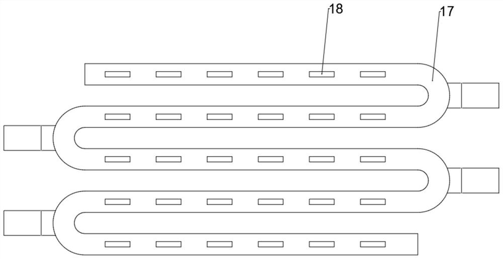
[0038] see Figure 4 , the side wall of the slide rail 17 is provided with a slide groove 19, the slide groove 19 is adapted to the pulley 203 of the slide block 20, so that the pulley 203 rotates along the slide groove 19 and drives the slide block 20 to move on the slide rail 17, and the slide rail 17 A support rod 16 is fixed at each bend, and each bend of the slide rail 17 is prone to damage. The support rod 16 can give the slide rail 17 a stable support force, and the slide rail 17 can operate more stably.
[0039] The difference from Example 1 is that
Embodiment 3
[0041] see figure 1 , Figure 4 and Figure 5 The slider 20 includes a pulley 203 slidingly connected to the slide rail 17, the pulley 203 is fixedly connected to the drive rod 202, the side walls on both sides of the slider 20 are provided with protrusions 201, and the inner wall of the slider 20 is provided with a groove 204, The groove 204 is provided with a push rod one 205, the end of the push rod one 205 is fixed with a connecting pipe 206, the upper surface center of the connecting pipe 206 is provided with a connecting sleeve 207, and the lower surface of the connecting pipe 206 is provided with a flexible pipe 208. The tube 208 has good elasticity, and it will not be damaged when stretched under the rotation of the rotating arm 2019. A horizontal plate 209 is fixed between the inner walls of the slider 20, and diagonal bars 2010 are symmetrically distributed on the inner wall of the slider 20. The clamping block 2014 is provided with a cavity 2015 suitable for the c...
PUM
 Abstract
Description
Claims
Application Information
 - R&D
- Intellectual Property
- Life Sciences
- Materials
- Tech Scout
- Unparalleled Data Quality
- Higher Quality Content
- 60% Fewer Hallucinations
Browse by: Latest US Patents, China's latest patents, Technical Efficacy Thesaurus, Application Domain, Technology Topic, Popular Technical Reports.
© 2025 PatSnap. All rights reserved.Legal|Privacy policy|Modern Slavery Act Transparency Statement|Sitemap|About US| Contact US: help@patsnap.com


