Novel calibration method for bridge support device in operation period

A calibration method and bridge bearing technology, applied in bridges, bridge parts, measuring devices, etc., can solve the problem that the service life of the intelligent monitoring bearing is not as good as that of the bridge bearing body due to the sensing device, so as to achieve easy modular design, guarantee Accuracy and reliability, the effect of easy removal and installation of the sensing device

Active Publication Date: 2020-11-27
DATONG INC
View PDF10 Cites 11 Cited by
  • Summary
  • Abstract
  • Description
  • Claims
  • Application Information

AI Technical Summary

Problems solved by technology

[0003] The service life of the intelligent monitoring bearing is far less than that of the bridge bearing body due to the sensing device, because there is inevitably replacement during the operation process, and the inheritance of the data of the sensing device before and after the replacement, and the accuracy of the monitoring data of the sensing device after the replacement and reliability, there is currently no effective way to conduct on-site verification

Method used


Image

  • Novel calibration method for bridge support device in operation period
  • Novel calibration method for bridge support device in operation period
  • Novel calibration method for bridge support device in operation period

Examples


Embodiment 1

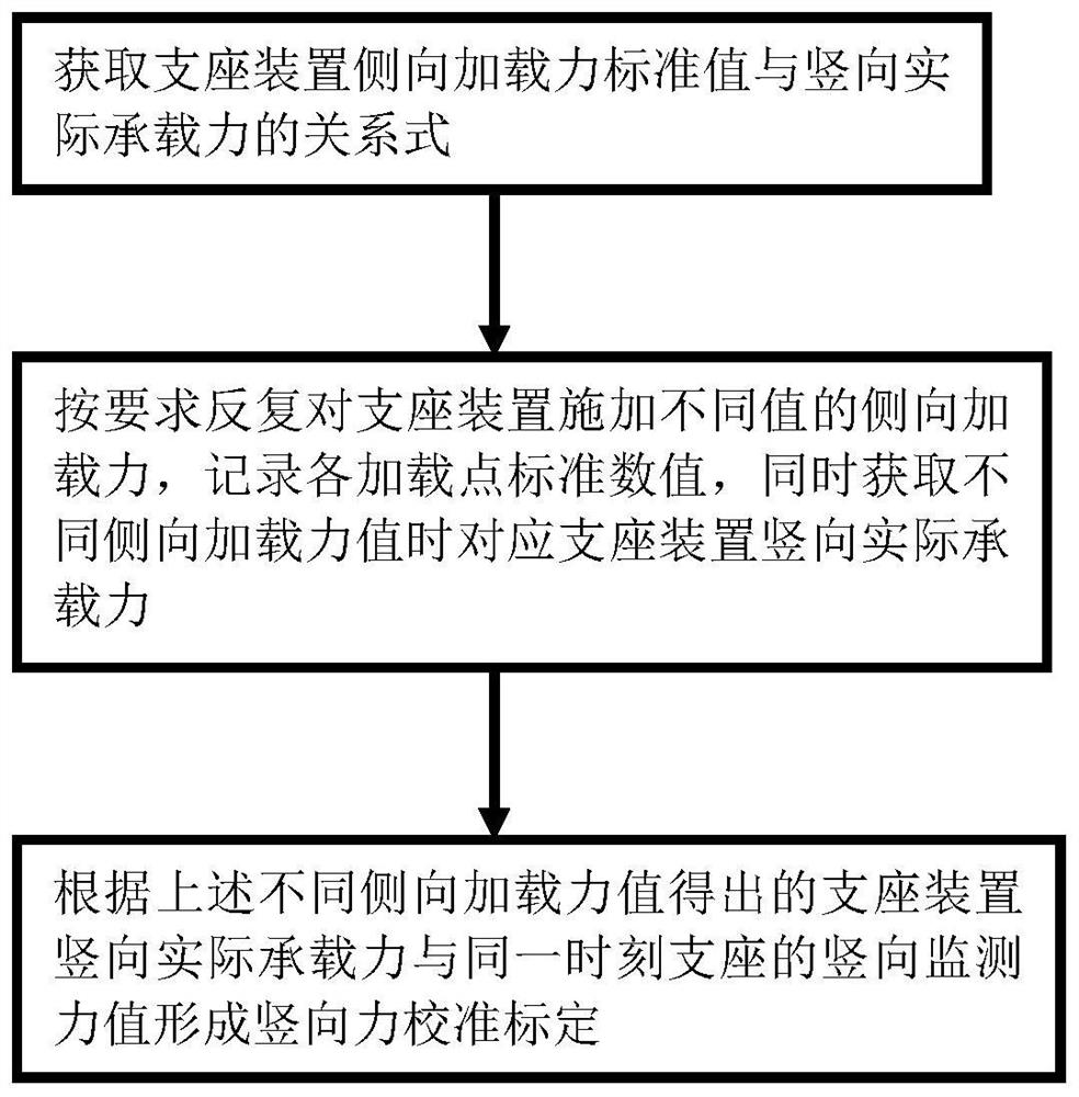
[0034] like figure 1 As shown, a new calibration method for bridge support devices during the operation period includes the following steps:

[0035] S1: Obtain the relationship between the standard value of the lateral loading force of the support device and the actual vertical bearing capacity;

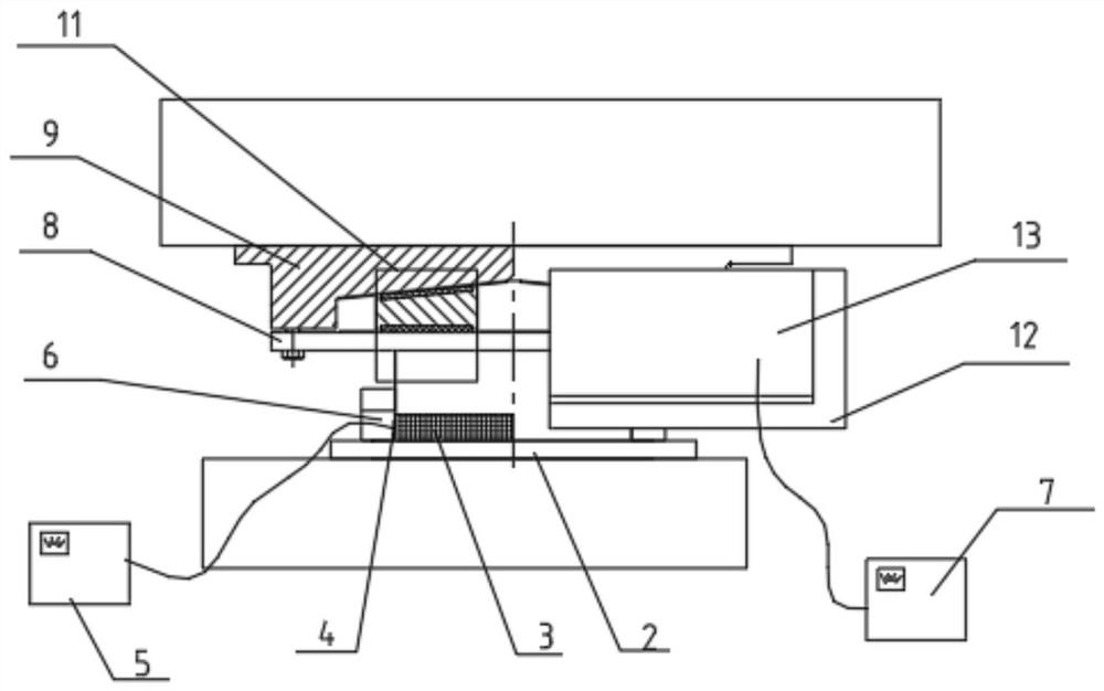
[0036] S2: Using the relational expression in S1 above, by connecting the power drive device 10 to the support device, the controller 7 is connected to the power drive device 10, and the controller 7 controls the power drive device 10 to repeatedly control the support device as required. Apply different values ​​of lateral loading force, such as C1, C2, C3, that is, apply horizontal force to the two adjustment blocks 14 of the height adjustment mechanism. The adjustment block 14 is wedge-shaped, similar to a triangle shape, and the height adjustment mechanism can completely feed back the vertical force to the The bearing body 1, according to the decomposition of the force, decompos...

Embodiment 2

[0039]The height adjustment mechanism is installed on the support, and the height adjustment mechanism moves away or approaches each other through the two adjustment blocks 14 to make the height adjustment mechanism rise or fall, and the power drive device 10 is connected to the two adjustment blocks, and can be adjusted when lateral loading force is applied. The corresponding relationship between the height value and the relative displacement value of the two adjusting blocks 14, and then the corresponding relationship between the relative displacement value of the two adjusting blocks 14 and the lateral loading force value is obtained, which is equivalent to replacing the relative displacement value of the adjusting block, thereby obtaining the height adjustment mechanism. The relationship between the appreciation and the lateral loading force value, such as when applying different lateral loading forces C1, C2, and C3 to the two adjusting blocks 14, measure and record the rel...

Embodiment 3

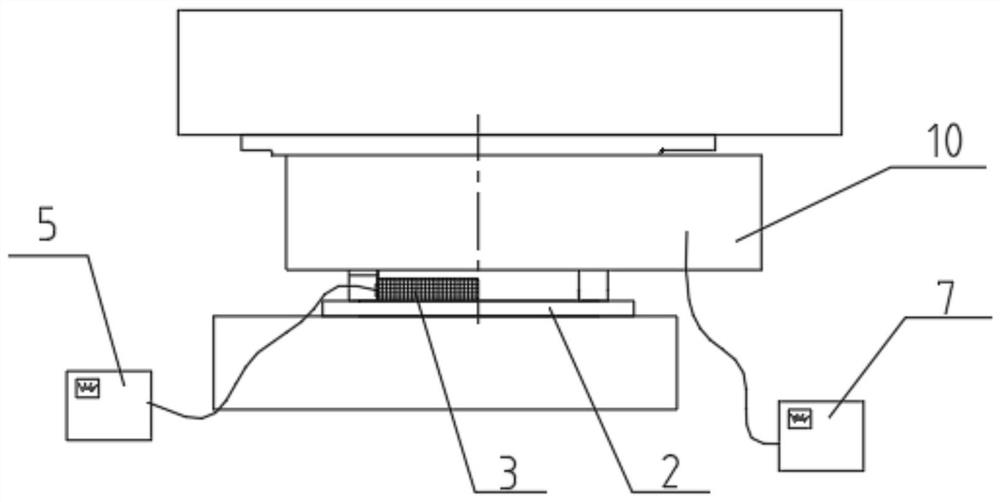
[0041] like Figure 2-4 As shown, a support device includes a support body 1. In this embodiment, a height adjustment mechanism is provided on the top surface of the support body 1. The height adjustment mechanism is installed on the bottom surface of the beam body, and the support body 1 is placed on a pelvic cavity. In the bottom basin 2 of the structure, the bottom basin 2 is installed on a bridge pier or a pier column, and a force-measuring carrier 3 is provided on the bottom surface of the support body 1. The force-measuring carrier 3 is closely attached to the inner wall of the pelvic cavity. A sensing device 4 is installed, and a mounting hole 6 is provided on the side of the bottom basin 2 to facilitate the installation of the sensing device 4 to achieve the purpose of easy disassembly and installation. The operator can directly touch whether the sensing device 4 is installed in place, and the sensing device The signal line of 4 is connected to the external data acquis...


PUM


Abstract

The invention discloses a novel calibration method for a bridge support device in an operation period. The method comprises the following steps: acquiring a relational expression between a lateral loading force standard value and a vertical actual bearing capacity of a support device, repeatedly applying lateral loading forces with different values to the support device according to requirements,recording standard values of loading points, and simultaneously acquiring the vertical actual bearing capacity of the corresponding support device when the lateral loading force values are different;and forming vertical force calibration according to the actual vertical bearing capacity of the support device obtained according to the different lateral loading force values and the vertical monitoring force value of the support at the same moment. A height adjusting mechanism is arranged on the top face of a support body, the support body is placed in a bottom basin with a basin cavity structure, a force measuring bearing body is arranged on the bottom face of the support body, a sensing device is installed on the side face of the force measuring bearing body, and a signal line of the sensing device penetrates through the side wall of the bottom basin to be connected with an external data collecting system. According to the invention, the accuracy and reliability of monitoring data after the support sensing device is replaced can be ensured, and the height of the support can be accurately adjusted.

Description

technical field [0001] The invention relates to the technical field of bridge engineering, in particular to a novel calibration method for a bridge support device during operation. Background technique [0002] The bridge bearing is the main force-transmitting component directly between the upper structure and the lower structure of the bridge structure. The change of the bearing force can largely reflect the overall operation of the bridge, and realize the monitoring data collection of the bridge bearing, that is, the vertical reaction force of the bridge. , which can provide a technical basis for bridge health monitoring. With the increase of highway and railway bridge construction in our country year by year, the monitoring of the vertical static load and dynamic load of the bridge bearing has important practical significance for the operation of the bridge. [0003] The service life of the intelligent monitoring bearing is far less than that of the bridge bearing body d...

Claims


Application Information

Patent Timeline
Patent Type & Authority Applications(China)
IPC IPC(8): G01M5/00E01D19/04
CPCE01D19/048G01M5/0008G01M5/005
Inventor 伍大成邹贻军王剑明胡盟
Owner DATONG INC
Why Eureka
Try Eureka