Inner hexahedron punching manufacturing method

A manufacturing method and hexahedron technology, applied in the field of punching manufacturing, can solve the problems of semi-finished parts impact, matrix deformation, influence, etc.

Pending Publication Date: 2020-11-27
SUZHOU SABO IND DESIGN
View PDF0 Cites 2 Cited by
  • Summary
  • Abstract
  • Description
  • Claims
  • Application Information

AI Technical Summary

Problems solved by technology

Punching requires prefabricated bottom holes, and the punching process is arranged after the previous machining, which will bring greater impact to the matrix of semi-finished parts, resulting in deformation of the matrix, especially for slender rods, the punching force is too high The assembly causes the disappearance of the precision of the front processing
However, in screw-in cartridge valves and hydraulic servo control system devices, there are a large number of precise and slender rods used for adjustment, feedback, and fastening. Due to the limitations of their own structural characteristics and application occasions, the tightening can only be adjusted in the form of an inner hexahedron. At the same time, due to the influence of precision requirements, the center-type precision CNC machine tool can only be used to process all the other geometric elements except the inner hexahedron at one time, and finally the inner hexahedron is processed by hydraulic press alone
The cutting force when punching the inner hexahedron directly affects the precision formed by the previous processing and the design requirements for the strength of the part itself. The diameter of the prefabricated bottom hole in traditional punching is smaller than the opposite side size of the inner hexahedron. According to the traditional inner hexahedron structure After the basic size is selected, the punching force is also determined. In order to avoid punching deformation, the radial dimension of the matrix will be increased according to the punching force during design, resulting in material waste and unnecessary impact on other designs

Method used


Image

  • Inner hexahedron punching manufacturing method
  • Inner hexahedron punching manufacturing method
  • Inner hexahedron punching manufacturing method

Examples


Embodiment Construction

[0068] In order to make the technical means, creative features, goals and effects achieved by the present invention easy to understand, the present invention will be further described below in conjunction with specific illustrations.

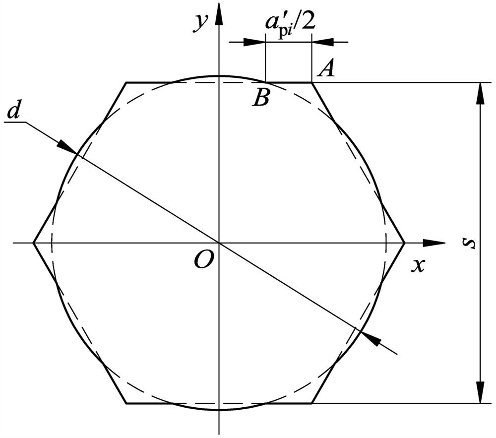
[0069] see Figure 1 to Figure 8 The internal hexahedron punching manufacturing method, the specific steps are as follows:

[0070] 1. Determine the technical scheme for reducing the cutting force of the inner hexahedron punching manufacturing method

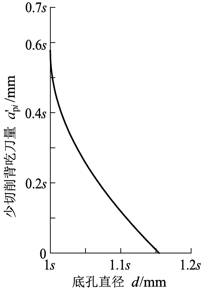
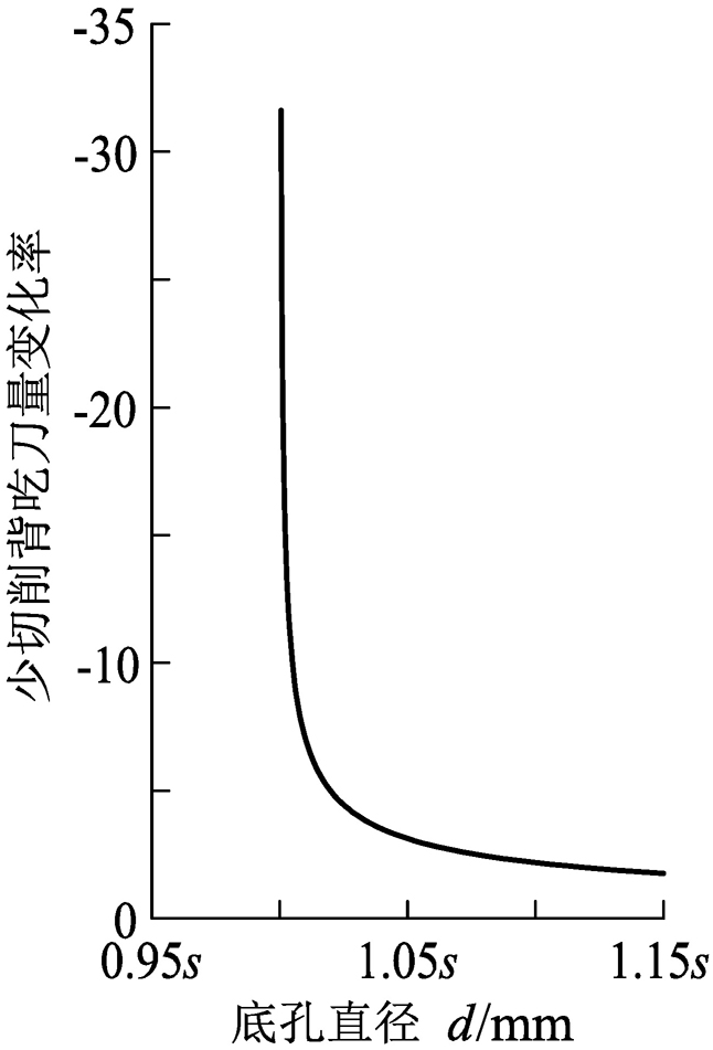
[0071] Based on the previous machining process, it is determined to increase the diameter of the prefabricated bottom hole to reduce the amount of back cutting during punching. The diameter of the prefabricated bottom hole in the less-cutting manufacturing method is larger than the corresponding side-to-side size of the inner hexahedron, which can be achieved. The amount of back cutting is reduced, and the cutting force is also reduced.

[0072] 2. Establish a less-cutting model of the inner hex...


PUM


Abstract

The invention discloses a few-cutting manufacturing method for an inner hexahedron. The method comprises the steps that firstly, the back engagement of the cutting edge is reduced by enlarging a prefabricated bottom hole, so that the purpose of reducing cutting force is achieved, then the change characteristic of the method is analyzed by establishing a small-cutting-amount model, the minimum backengagement of the cutting edge during manufacturing is determined according to the manufacturing error standard of an inner hexahedron and a wrench, and finally the reasonable back cutting depth andthe diameter of a prefabricated bottom hole are controlled in an amplification coefficient or optimization coefficient mode according to loads. A few-cutting manufacturing method is adopted for machining the inner hexahedron, on the premise that the using performance of the inner hexahedron is guaranteed, the cutting force is reduced, precision reduction caused by too large punching force is eliminated, interference on the strength design of parts is avoided, and meanwhile manufacturing energy consumption is reduced.

Description

technical field [0001] The invention relates to the technical field of punching manufacturing, in particular to a punching manufacturing method of an inner hexahedron. Background technique [0002] The batch production of standard fasteners such as screws and bolts with internal hexahedrons mostly adopts the upsetting method, and the small-quantity trial production or special-shaped non-standard products that are not suitable for upsetting due to process restrictions generally use punching. Punching requires prefabricated bottom holes, and the punching process is arranged after the previous machining, which will bring greater impact to the matrix of semi-finished parts, resulting in deformation of the matrix, especially for slender rods, the punching force is too high The assembly causes the disappearance of the precision of the front processing. However, in screw-in cartridge valves and hydraulic servo control system devices, there are a large number of precise and slender...

Claims


Application Information

Patent Timeline
Patent Type & Authority Applications(China)
IPC IPC(8): G06F30/17B21D22/02G06F119/14
CPCB21D22/02G06F30/17G06F2119/14
Inventor 张祝肖名涛沈陆明
Owner SUZHOU SABO IND DESIGN
Why Eureka
Try Eureka