Industrial camera for electric welding monitoring

An industrial camera and camera technology, which is applied to color TV parts, TV system parts, TVs, etc., can solve the problems that the filtering range has an upper limit, it is difficult to achieve strong light suppression, and achieve simplified algorithms and hardware requirements. Reduced processor and other hardware requirements, easy to implement effects

Inactive Publication Date: 2020-11-27
杭州艾洋洋信息科技有限公司
View PDF5 Cites 0 Cited by
  • Summary
  • Abstract
  • Description
  • Claims
  • Application Information

AI Technical Summary

Problems solved by technology

[0008] This type of method adds an electronically controlled liquid crystal filter to the camera lens, and switches the light transmittance of the liquid crystal according to the light value measured by the optical sensor, so as to achieve the effect of shooting non-welding and welding arcs at the same time, but the problem is that the liquid crystal dimming mirror There is a threshold value for the minimum light transmittance, that is, its filtering range has an upper limit, and it can only be switched among a few discrete light transmittances, while the welding arc intensity changes continuously, and the captured images are divided into different light and dark Several sections, still need some post-processing
However, during the welding process, the position of the solder joint is constantly changing, and the angle of the brightness sensor is constantly changing, so that the detection value is in a dynamic error, and it is not easy to achieve the ideal strong light suppression.

Method used


Image

  • Industrial camera for electric welding monitoring
  • Industrial camera for electric welding monitoring
  • Industrial camera for electric welding monitoring

Examples


Embodiment Construction

[0038] The present invention will be further described below in conjunction with embodiment.

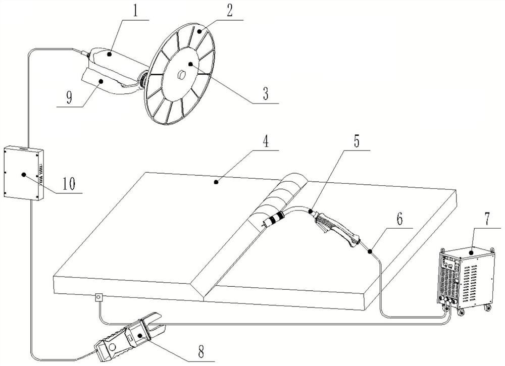
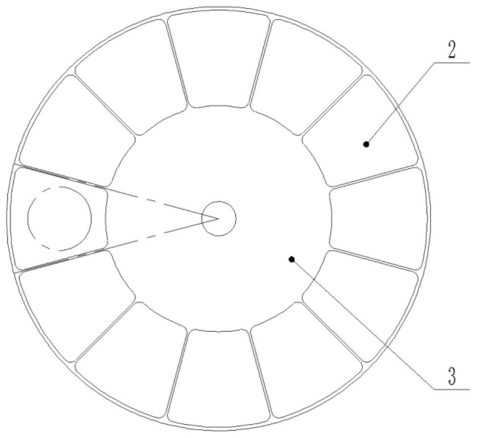
[0039] Such as Figure 1-2 As shown, an industrial camera for electric welding monitoring includes a camera 1, a filter disc 3 installed at the front end of the camera 1, a control box 10 and a camera adjustment box 9, and the filter disc 3 is provided with a plurality of filters with different concentrations Optical sheet 2, optical filter 2 is arranged in the circumferential direction of the outer edge of filter disc 3, optical filter 2 coincides with or is parallel to the optical path of the lens of camera 1, and the camera can pass through the optical filter to take images during electric welding, and said filter disc 3 Rotatable, only one optical filter 2 coincides with the lens optical path of the camera 1 at any time;

[0040] The control box 10 measures the current generated when the electric welding equipment works, and controls the rotation of the filter disc 3 in real tim...


PUM


Abstract

The invention relates to an industrial camera for electric welding monitoring. The camera includes a camera, a welding gun and an electric welding machine, the electric welding machine is connected with a weldment and the welding gun through cables; the industrial camera is provided with a plurality of groups of optical filters with different concentrations; the optical filters are arranged in thecircumferential direction of the outer edge of the optical filter disc; the camera can shoot an electric welding position through the optical filter; the optical filter disc can rotate and is switched into an optical filter for filtering of the camera; the industrial camera further comprises a non-contact electric meter which is used for detecting electrical parameters on a cable, the non-contactelectric meter, the optical filter disc and the camera are all electrically connected with the control box, and the control box correspondingly controls movement of the optical filter disc accordingto read data detected by the non-contact electric meter. According to the scheme, a brightness sensor is replaced by detection of electrical parameters of the electric welding cable, the influence ofenvironmental factors such as a camera shooting angle on strong light inhibition is overcome, and meanwhile, an accessed optical filter is accurately switched by adopting an optical filter disc system, so that the brightness of a picture is always approximately consistent no matter whether strong light exists or not.

Description

technical field [0001] The present application relates to industrial security and monitoring equipment, in particular to an industrial camera for electric welding monitoring. Background technique [0002] In the welding process of mechanical manufacturing, strong and unstable arc light will be generated at the welding position. For analysis or safety purposes, it is necessary to photograph the welding location and, when not welding, to photograph the working conditions of the welding crew. Among the prior art, the light-sensing range of the camera is very small (only a part of the daily light range), beyond this range, it is necessary to use a supplementary light or a black film to reduce the luminosity. However, the luminosity range of the arc light during the electric welding process is too large and too fast, and there are still certain problems in the suppression of strong light. [0003] Some strong light suppression methods for electric welding have appeared in the p...

Claims


Application Information

Patent Timeline
Patent Type & Authority Applications(China)
IPC IPC(8): H04N5/225H04N5/232F16M11/04F16M11/10F16M11/18G01R19/00
CPCG01R19/0092F16M11/048F16M11/10F16M11/18H04N23/55H04N23/695
Inventor 刘俊
Owner 杭州艾洋洋信息科技有限公司
Why Eureka
Try Eureka