
Cleaning machine and path planning method of cleaning machine

A path planning, cleaning machine technology, applied in cleaning methods and utensils, cleaning methods using liquids, cleaning machinery, etc., can solve problems such as inability to effectively clean coffee stains

Active Publication Date: 2020-08-07
HOBOT TECH INC
View PDF7 Cites 5 Cited by
  • Summary
  • Abstract
  • Description
  • Claims
  • Application Information

AI Technical Summary

Problems solved by technology

However, such a cleaning method cannot effectively clean stains such as coffee, water, oil or ink, so there is room for further improvement

Method used


Image

  • Cleaning machine and path planning method of cleaning machine
  • Cleaning machine and path planning method of cleaning machine
  • Cleaning machine and path planning method of cleaning machine

Examples


Embodiment Construction

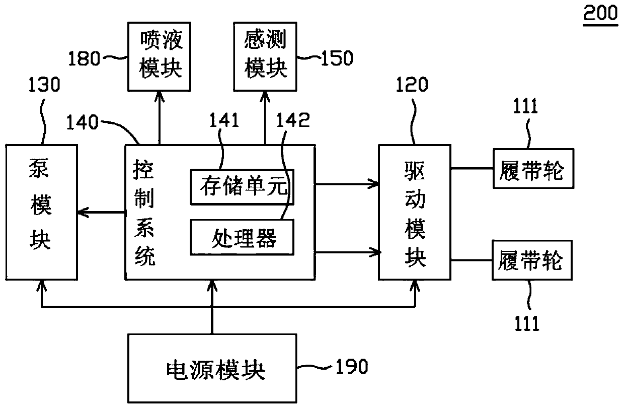
[0070] figure 2 It is a functional block diagram of a cleaning machine according to an embodiment of the present invention. Please refer to figure 2 In this embodiment, the cleaning machine 200 includes a power module 190 , a sensing module 150 , a pump module 130 , a driving module 120 and a control system 140 . The control system 140 includes a processor 142 and a storage unit 141 . The power module 190 is electrically connected to the pump module 130 , the driving module 120 and the control system 140 to provide a power supply. In one embodiment, the power supply module 190 can be a battery module, which further includes a power sensing module (not shown). When the power of the cleaning machine 200 is insufficient, the power sensing module will emit a warning sound or a warning light or automatically return to the charging station for charging. In one embodiment, the power module 190 of the cleaning machine 200 may include a power cord to be electrically connected to ...


PUM


Abstract

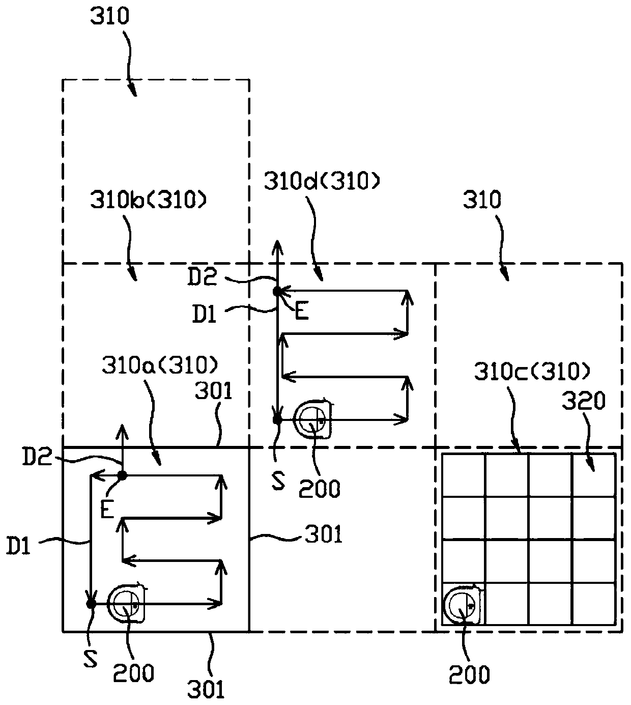
The invention provides a cleaning machine and a path planning method of the cleaning machine, and according to one embodiment of the invention, the cleaning machine is used for cleaning a surface. Thecleaning machine comprises a sensing module and a control system. The sensing module is used for sensing the environment of the cleaning machine to obtain map data. The control system is used for dividing the map data into a plurality of blocks and enabling the cleaning machine to perform a first cleaning program and a second cleaning program in a current block of the blocks and then walk to thenext block.

Description

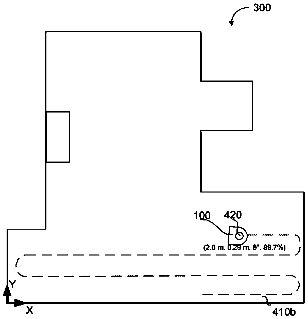
technical field [0001] The present invention relates to a cleaning machine and a cleaning machine path planning method, in particular to a cleaning machine using a cleaning liquid to clean a surface and a cleaning machine path planning method. Background technique [0002] The mobile cleaning robot uses ranging sensors, mechanical contact sensors, or non-contact ranging sensors to build a map and locate itself in the map, so that the cleaning robot can determine its position in the surrounding environment and orientation, and plan the cleaning path. [0003] figure 1 A schematic diagram showing a prior art path planning method. figure 1 A schematic diagram showing the path planning method disclosed in International Patent Publication No. WO2016148743A1. Such as figure 1 As shown, according to the prior art, the robot 100 uses sensors to measure the walls of the room 300, and performs wall-following behavior along the walls in the room 300, and makes a map after making a ...

Claims


Application Information

Patent Timeline
Patent Type & Authority Applications(China)
IPC IPC(8): A47L11/24A47L11/28A47L11/40G05D1/02
CPCG05D1/0236G05D1/024G05D1/0242G05D1/0246A47L11/24A47L11/28A47L11/408G05D1/0274B08B3/024G05D1/0272G05D1/0219B25J9/1664B25J11/0085
Inventor 赵志谋
Owner HOBOT TECH INC
Learn More