

Mincing, kneading and pressing device for meat product processing
A technology for meat products and working racks, which is applied in the field of meat product production equipment, can solve the problems of manpower consumption and low efficiency, and achieve the effects of improving efficiency, convenient cleaning of discharge materials, and stable operation
- Summary
- Abstract
- Description
- Claims
- Application Information
AI Technical Summary
Problems solved by technology
Method used
Image

Examples
Embodiment 1
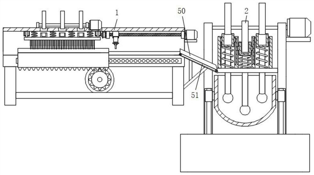
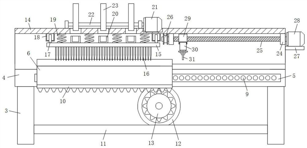
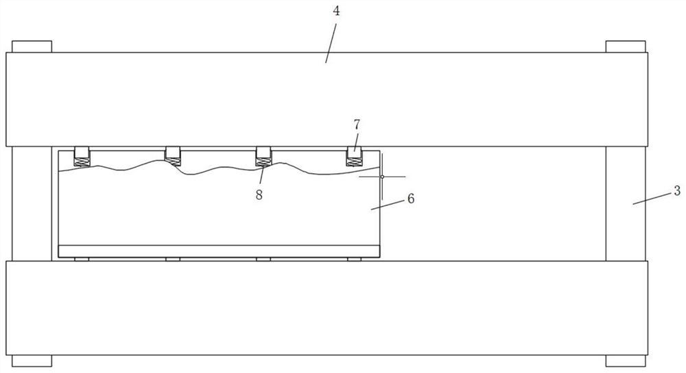
[0032] refer to Figure 1-5 , a crushing and kneading device for processing meat products, comprising a chopping mechanism 1 and a kneading and pressing mechanism 2, the chopping mechanism 1 includes a support seat 3, and mounting beams 4 are fixed on the front and rear sides of the top of the support seat 3, and the two pieces are installed One end of the beam 4 close to each other is provided with a mounting groove 5, and a cutting table 6 is slidably connected between the two mounting grooves 5, and a groove is also provided at the front and rear ends of the cutting table 6, and the inner wall of the groove is slidably connected with a clamping block 7. An extruding spring 8 is fixed between the block 7 and the bottom surface of the groove, and the bottom side of the installation groove 5 is also provided with a draw-in groove 9, and the block 7 is placed in the draw-in groove 9, and the bottom surface of the cutting table 6 is also fixed with a rack 10 , the inner sides of...
Embodiment 2
[0035] Such as figure 1 As shown, this embodiment is basically the same as Embodiment 1. Preferably, the work frame 14 is also provided with a material guide frame 50 near the end of the horizontal plate 27, and the material guide frame 50 is fixed on the side wall of the support seat 3. The material guide frame 50 The other end passes through the vertical plate 33 and extends to the position on the upper side of the kneading barrel 38. The inner bottom surface of the material guide frame 50 is also provided with a rectangular groove, and the front and rear end inner walls of the rectangular groove are rotatably equipped with a conveyor belt 2 51.
[0036] In this embodiment, the conveyer belt 2 51 is installed inside the inner bottom surface of the material guide frame 50, so as to facilitate the transportation of the chopped minced meat to the kneading and pressing barrel 38, thereby realizing automatic feeding operation.
Embodiment 3
[0038] Such as Figure 1-3 As shown, this embodiment is basically the same as Embodiment 1. Preferably, two support bases 3 are arranged and stacked symmetrically and fixed on both sides of the working surface.
[0039] There are multiple clamping blocks 7 and they are evenly distributed inside the front and rear end side walls of the cutting table 6 , and there are multiple clamping slots 9 and they are evenly distributed on the bottom surface of the installation groove 5 .
[0040] In this embodiment, a plurality of locking slots 9 are uniformly opened on the bottom surface of the installation slot 5, so that the cutting table 6 can be temporarily fixed after moving, thereby ensuring the stability of the device when the meat is cut and unloaded.
PUM
 Abstract
Description
Claims
Application Information