
Eureka
For R&D, Eureka makes reading and utilizing patents & technical documents easy.
Eureka AIR
Designed for self-driven R&D workflows. Generate viable solutions, solve complex R&D challenges, empower your innovation with AI.

Eureka Materials
Designed for material experts only. Revolutionize your material R&D, from search, analyze, to developing new materials.

TechResearch
Generate reliable direction feasibility study reports for your R&D in just a few steps.

TechSeek
Discover and master advanced knowledge NOW. Basics, ideas, possibilities, all at once.

TechMind
As an expert in R&D Theories, TechMind can generates customized viable solutions instantly.

TechRisk
Analyze your overall solution with one click, know your potential R&D risks in advance.

TechMonitor
Get weekly tech updates, stay abreast of the latest tech innovations and key insights.
Automatic concrete feeding and stirring device
An automatic feeding and mixing device technology, which is applied in the direction of cement mixing device, unloading device, clay preparation device, etc., can solve the problems of slow concrete efficiency, slow mixing effect and unsatisfactory mixing effect, and achieve the goal of improving efficiency and improving mixing effect Effect
- Summary
- Abstract
- Description
- Claims
- Application Information
AI Technical Summary
Problems solved by technology
Method used
Image

Examples
Embodiment 1
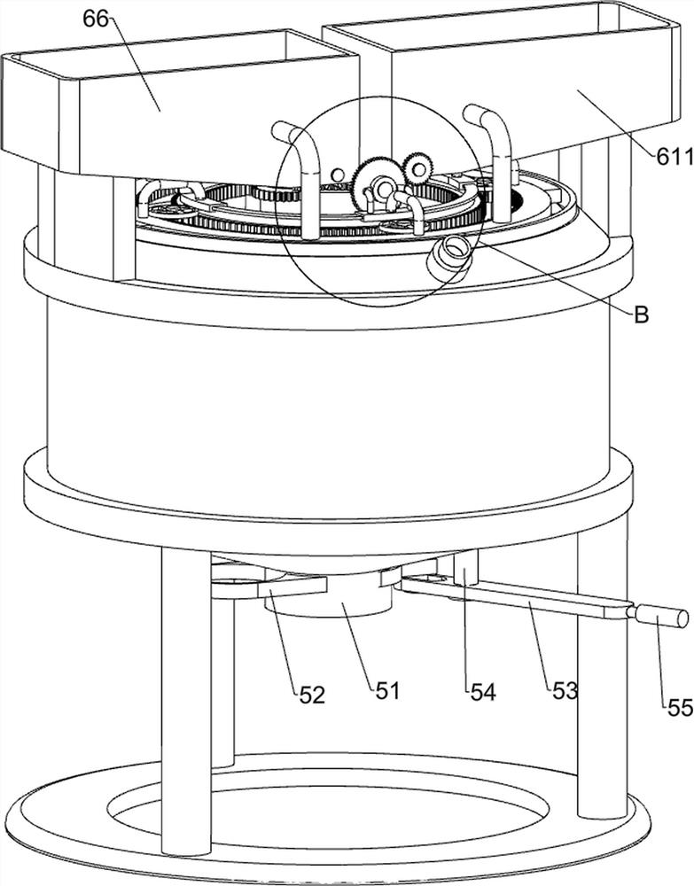
[0025] A concrete automatic feeding and mixing device, such as Figure 1-6 As shown, it includes a base plate 1, a support frame 2, a mixing tank 3, a stirring mechanism 4 and a valve mechanism 5, the top of the base plate 1 is connected with a support frame 2, the upper part of the support frame 2 is connected with a mixing tank 3, and the top of the mixing tank 3 is provided with A stirring mechanism 4 is provided, and a valve mechanism 5 is arranged at the bottom of the mixing barrel 3 .
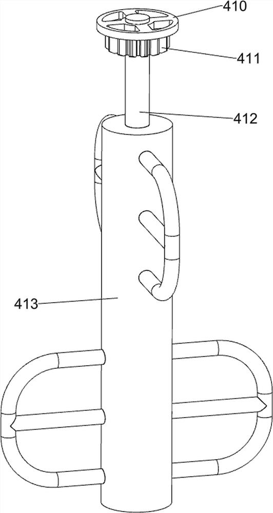
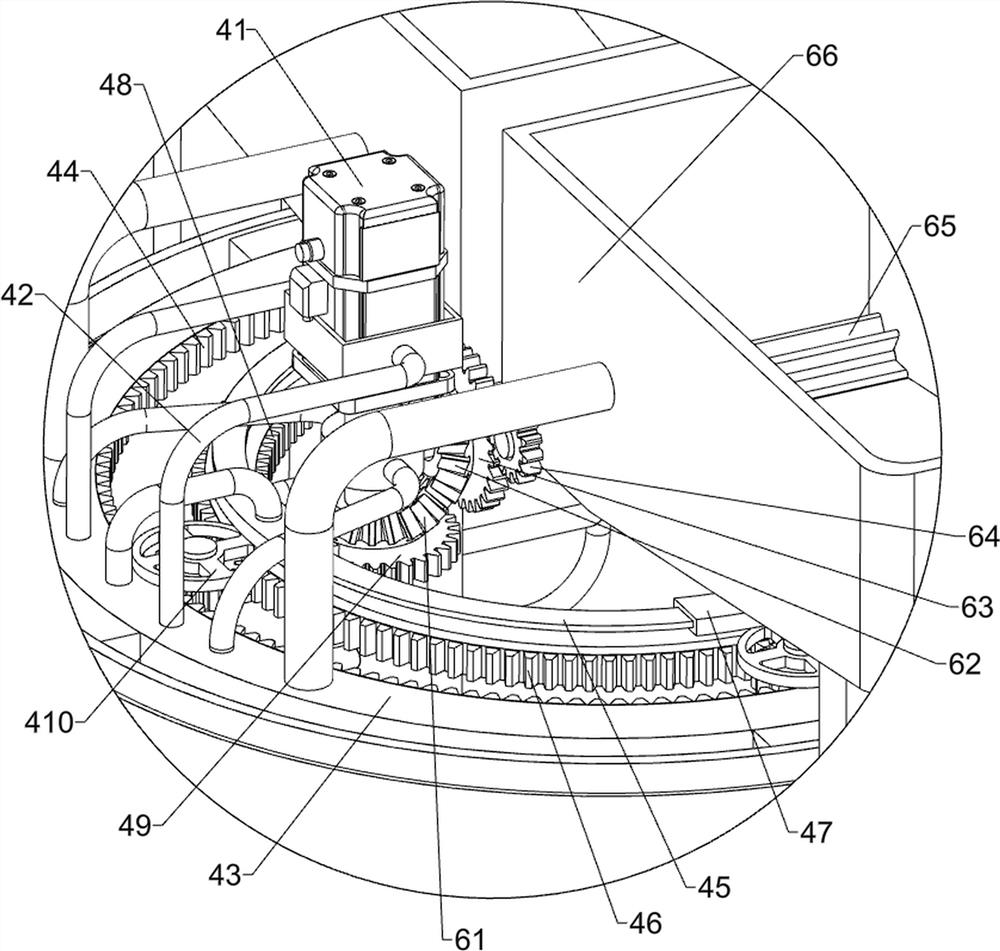
[0026] The stirring mechanism 4 includes a servo motor 41, a connecting frame 42, a fixed ring 43, a first rack ring 44, a sliding ring 45, a second rack ring 46, a fixed guide rail 47, a third rack ring 48, and a first gear 49 , limit plate 410, second gear 411, connecting rod 412 and stirring frame 413, the top of mixing bucket 3 is connected with fixing ring 43, the middle of fixing ring 43 rear side top is connected with connecting frame 42, and connecting frame 42 is equipped with se...
Embodiment 2
[0030] On the basis of Example 1, such as figure 2 , image 3 , Figure 5 and Figure 6 Shown, also include feeding mechanism 6, and feeding mechanism 6 includes first bevel gear 61, second bevel gear 62, the 3rd gear 63, the 4th gear 64, dial shaft 65, the first storage box 66 , transmission shaft 67, limit ring sleeve 68, the fifth gear 69, the sixth gear 610 and the second material storage box 611, the first bevel gear 61 is connected on the rotating rod, and the fixed guide rail 47 top on the front side is connected with limit ring Sleeve 68, the limit ring sleeve 68 is internally connected with transmission shaft 67, the front side of transmission shaft 67 is connected with the fifth gear 69, the rear side of transmission shaft 67 is connected with the third gear 63, and the rear end of transmission shaft 67 is connected with the second gear. Bevel gear 62, the second bevel gear 62 meshes with the first bevel gear 61, the left side of the support frame 2 top is connec...
Embodiment 3
[0033] On the basis of Example 2, such as Figure 1-2 As shown, a water pipe joint 7 is also included, and the upper part of the front side of the mixing bucket 3 is connected with a water pipe joint 7 .
[0034] The water pipe joint 7 can be connected to the external water pipe, so that water can enter the mixing tank 3 through the external water pipe and the water pipe joint 7, so that water is not manually poured into the mixing tank 3, thereby saving effort.
PUM
 Abstract
Description
Claims
Application Information
 - R&D Engineer
- R&D Manager
- IP Professional
- Industry Leading Data Capabilities
- Powerful AI technology
- Patent DNA Extraction
Browse by: Latest US Patents, China's latest patents, Technical Efficacy Thesaurus, Application Domain, Technology Topic, Popular Technical Reports.
© 2024 PatSnap. All rights reserved.Legal|Privacy policy|Modern Slavery Act Transparency Statement|Sitemap|About US| Contact US: help@patsnap.com