Double-pump confluence hydraulic system and excavator

A hydraulic system and double-pump confluence technology, applied in the field of double-pump confluence hydraulic system and excavator, can solve the problems of energy waste, high heat generation, large pressure loss, etc., and achieve short flow distance, small energy loss and small pressure loss Effect

Active Publication Date: 2020-12-01
SHANDONG LINGONG CONSTR MACHINERY
View PDF6 Cites 1 Cited by
  • Summary
  • Abstract
  • Description
  • Claims
  • Application Information

AI Technical Summary

Problems solved by technology

[0004]However, in the current dual-pump oil supply system, the two pumps respectively supply oil to the breaker through the main valve. When the oil flows through the main valve, due to the main v

Method used


Image

  • Double-pump confluence hydraulic system and excavator
  • Double-pump confluence hydraulic system and excavator
  • Double-pump confluence hydraulic system and excavator

Examples


Example

[0047] first embodiment

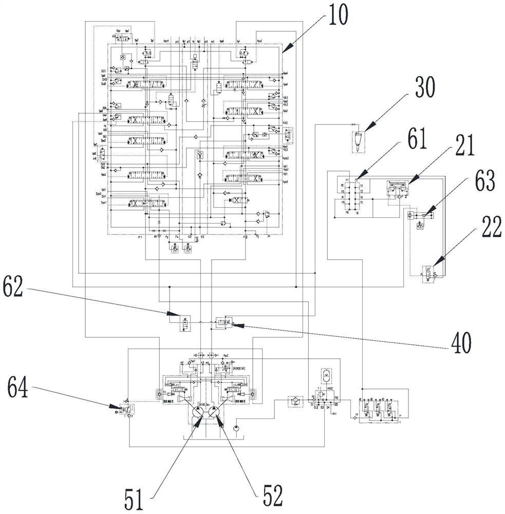
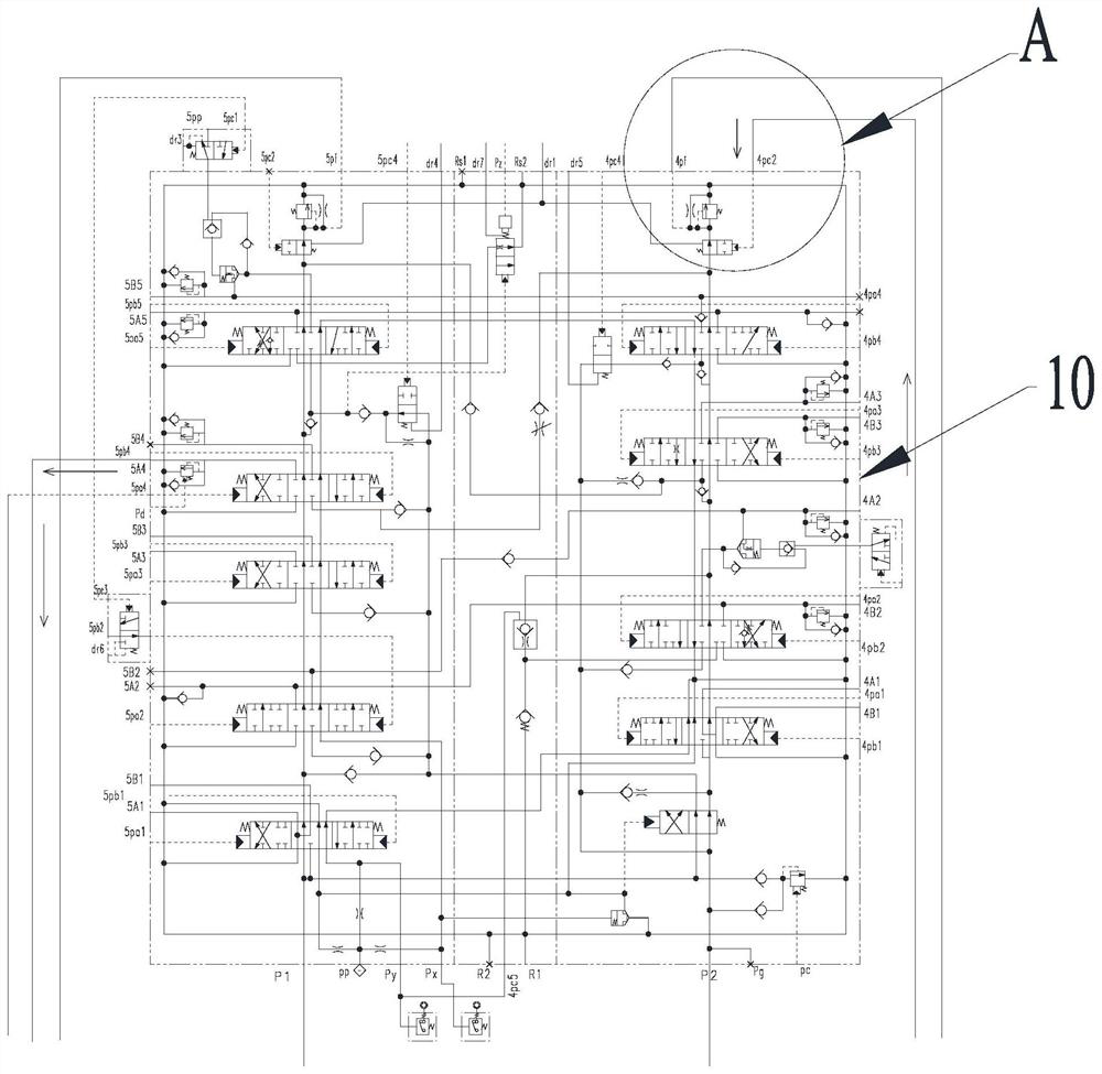
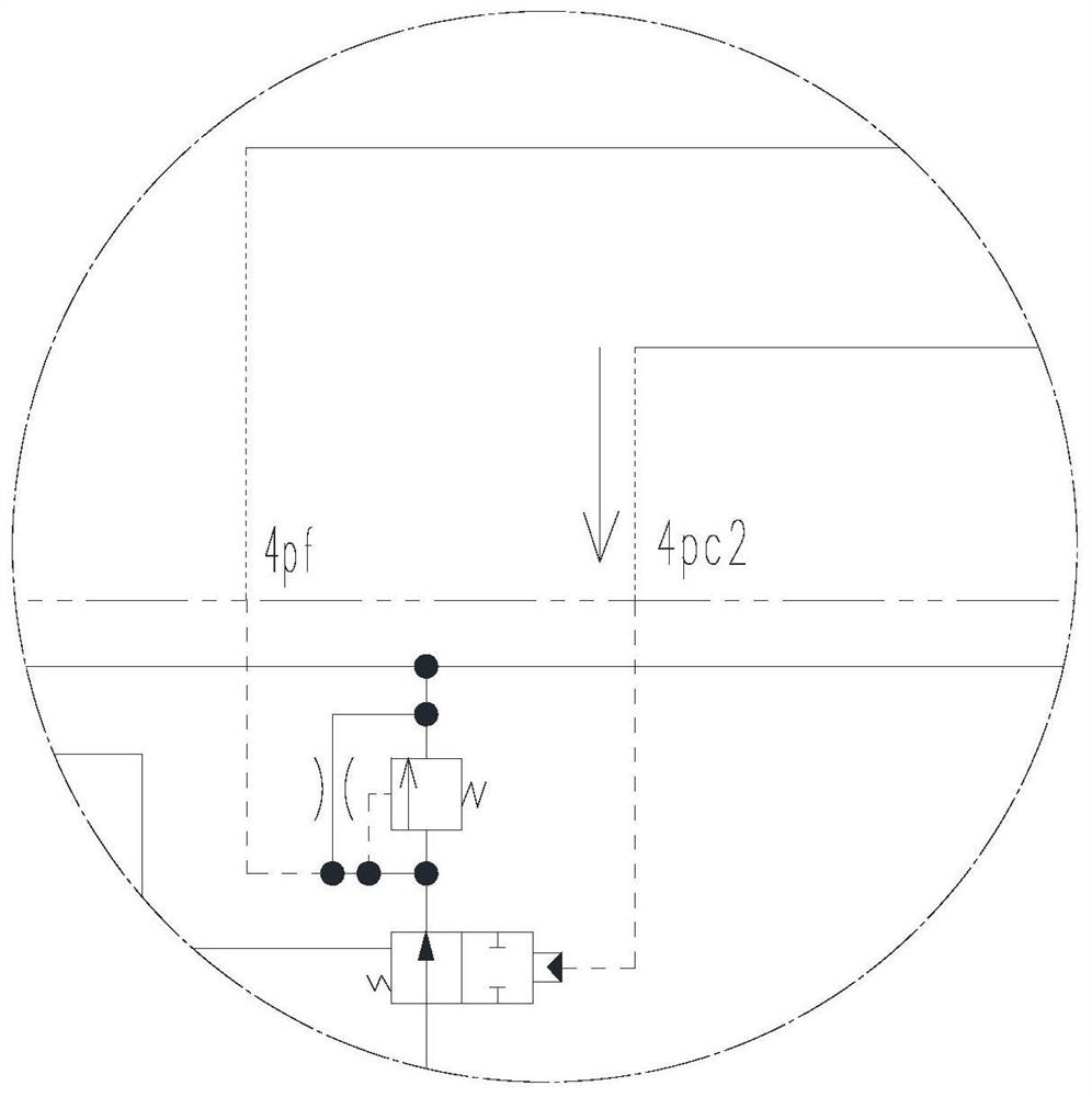
[0048] Please refer to figure 1 - Figure 5 , this embodiment provides a dual-pump confluence hydraulic system, which includes a pumping module, a breaker start module, a main valve 10 and a breaker 30, wherein:

[0049] The pumping module includes a first pumping mechanism 51 and a second pumping mechanism 52 , the main valve 10 includes a first valve block group and a second valve block group, the first pumping mechanism 51 and the first valve block group of the main valve 10 communication, the second pumping mechanism 52 communicates with the second valve block group of the main valve 10; in figure 1 Among them, the first valve block group is a row of valve blocks on the left side of the main valve 10 , and the second valve block group is a row of valve blocks on the right side of the main valve 10 . Each valve block in the main valve 10 is used to communicate with a number of different mechanisms in the excavator to supply oil to the various me...

Example

[0071] Second Embodiment

[0072] This embodiment provides an excavator, which includes the dual-pump confluence hydraulic system provided in the first embodiment.

[0073] Further, in the excavator provided in this embodiment, a control system is further included, and the control system is connected with the dual-pump confluence hydraulic system.

[0074]Specifically, the control system is connected to the pressure switch in the dual-pump confluence hydraulic system, and the pressure in the pilot oil pipeline is detected by the pressure switch to determine whether the pilot oil pipeline is connected to determine whether the breaker starting module is activated. When the breaker starting module is started, the control system switches the excavator to the crushing mode, and when the breaker starting module is not started, the control system switches the excavator to the digging mode. Specifically, in the crushing mode, the control system controls the engine in the excavator to...


PUM


Abstract

A double-pump confluence hydraulic system relates to the technical field of excavators and comprises a pumping module, a breaking hammer starting module, a main valve and a breaking hammer, wherein the pumping module comprises a first pumping mechanism and a second pumping mechanism, the first pumping mechanism communicates with a first valve block group of the main valve, and the second pumping mechanism communicates with a second valve block group of the main valve; the breaking hammer starting module communicates with a pilot oil pipeline; the pilot oil pipeline respectively communicates with a converging valve and a negative flow signal cut-off valve in the main valve; the breaking hammer communicates with a breaking hammer oil supply pipeline, the breaking hammer oil supply pipeline communicates with the first pumping mechanism in the pumping module through the main valve, and the breaking hammer oil supply pipeline communicates with the second pumping mechanism in the pumping module through the converging valve. When the double-pump confluence hydraulic system supplies oil to the breaking hammer, the first pumping mechanism supplies oil through the main valve, the second pumping mechanism supplies oil through the converging valve, the oil does not need to flow through the main valve, and the energy loss of the oil is reduced while the oil supply amount is increased through double-pump oil supply.

Description

technical field [0001] The invention relates to the field of excavators, in particular to a dual-pump confluence hydraulic system and an excavator. Background technique [0002] The main operating conditions of the excavator are shoveling, hoisting, and leveling operations, etc. After being replaced with a breaker, it can be used for crushing operations, and it is used in mining, metallurgy, roads, railways, construction and other working conditions. [0003] At present, part of the breaker installed on the excavator uses a single pump for oil supply, and the other part uses a double pump for oil supply. If the breaker adopts a single pump for oil supply, due to the limitation of single pump oil supply, the excavator can only be equipped with a breaker with a smaller drill rod, which cannot meet the oil supply demand of a breaker with a larger drill rod specification. In order to solve the above problems, some breakers use dual pumps to supply oil, and the two pumps in the ...

Claims


Application Information

Patent Timeline
IPC IPC(8): E02F9/22E02F5/30
CPCE02F9/22E02F9/2292E02F5/30
Inventor 迟峰张贵贤董立队刘崇张建石常增谢印标
Owner SHANDONG LINGONG CONSTR MACHINERY
Why Eureka
Try Eureka