Grease plunger pump

A plunger pump and dry oil technology, applied in the field of lubrication, can solve the problems of insufficient oil supply, large number of oil stirring parts, high power consumption, etc., achieve large oil supply, compact and reasonable structure, and shorten service life Effect

Inactive Publication Date: 2013-11-06
BEIJING CMRC SCI & TECH DEV
View PDF8 Cites 0 Cited by
  • Summary
  • Abstract
  • Description
  • Claims
  • Application Information

AI Technical Summary

Problems solved by technology

[0012] The present invention aims to solve the problems that the oil supply volume of the existing dry oil pump cannot meet the requirements and the number of oil stirring parts is large, the structure is complicated, and the power consumption is high. Herein, a kind of oil supply volume can be met, and the oil stirring parts are simplified at the same time. Dry oil plunger pump

Method used


Image

  • Grease plunger pump
  • Grease plunger pump
  • Grease plunger pump

Examples


Embodiment 1

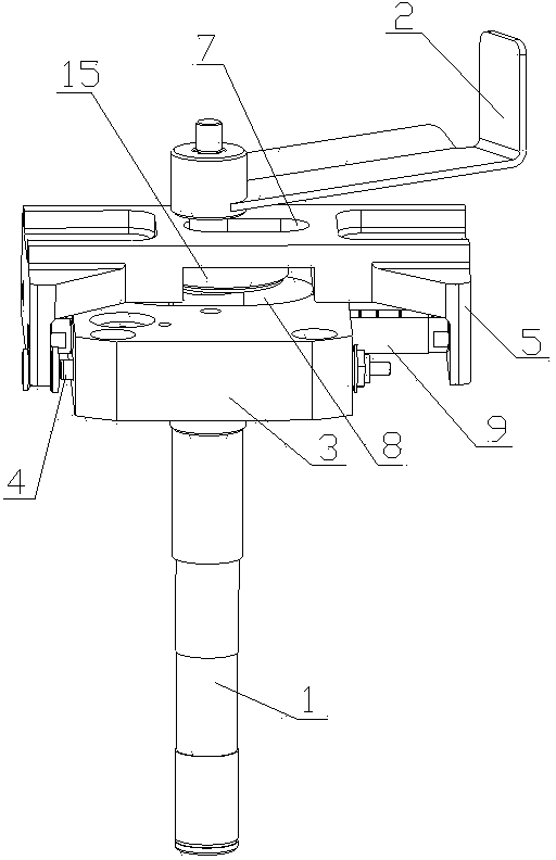
[0059] Combine figure 1 , 2 , 3 and 5, the dry oil plunger pump of the present invention includes a driving device 1, an oil stirring device 2, and an oil suction and discharge device. The driving device 1 provides power for the plunger pump to absorb, discharge and stir oil. The oil stirring device 2 is placed in the oil storage barrel and rotates circularly under the drive of the drive device 1 to achieve oil stirring. The oil suction and discharge device undertakes the oil suction of the plunger pump Working with oil discharge, it includes a pump body and a swing device.

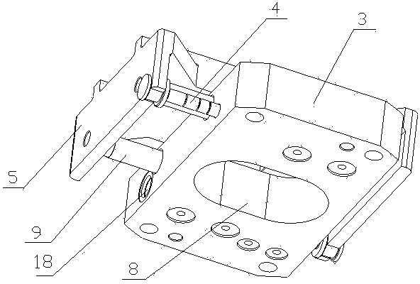
[0060] The pump body includes a cylinder 3 and a plunger 4 fixed in the plunger pump. The cylinder 3 is equipped with suction and discharge channels. The end of the cylinder 3 is provided with an oil suction port and an oil discharge port. The side of the cylinder 3 is provided with a plunger chamber 18. The oil suction and discharge passage connects the oil suction port, the oil discharge port and the plun...

Embodiment 2

[0065] Combine Figure 7 As shown, the difference between this embodiment and Embodiment 1 is that the driving device 1 is placed horizontally, and the rotation axis of the driving device 1 is perpendicular to the rotation axis of the oil stirring device 2. The rotating shaft of the driving device 1 passes through the first through hole 7 opened in the swing body 5 and the second through hole 8 opened in the cylinder 3, and the end is connected to the oil stirring device 2 through the reversing gear set 13 and drives the oil stirring device 2 Stir the dry oil continuously in the storage tank. By setting the gear ratio of the meshing gears in the reversing gear set, the reduction transmission can be realized, so that the oil stirring speed is slower than the pump oil speed, and the generation of air bubbles during the oil stirring process is effectively reduced.

[0066] In this embodiment, the driving device and the oil suction and discharge device are easier to separate or combi...

Embodiment 3

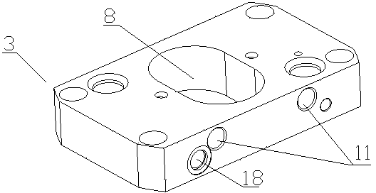
[0068] Combine image 3 As shown, the difference between this embodiment and embodiment 1 is that the second through hole 8 opened in the oil cylinder 3 is a waist-shaped through hole. The size of the waist-shaped through hole is such that the rotating shaft and the eccentric wheel of the driving device 1 are installed and disassembled. As a whole, 15 can easily pass through the second through hole 8, which effectively simplifies the installation and disassembly process of the equipment. Or as Figure 4 As shown, the second through hole 8 can also be set as an eccentric through hole to reduce the area of ​​the through hole on the cylinder 3. When the rotating shaft of the driving device 1 and the eccentric wheel 15 are in the range of the eccentric through hole, the driving device 1 The rotating shaft and the eccentric wheel 15 as a whole can easily pass through the second through hole 8.


PUM


Abstract

The invention relates to a grease plunger pump. The grease plunger pump comprises a driving device, a grease stirring device, and a grease absorption and discharging device, wherein the grease absorption and discharging device comprises a pump body and a swing device; the pump body comprises a cylinder and a plunger movably arranged in a plunger chamber of the cylinder; the swing device comprises a swing main body which can do reciprocating motion axially relative to the plunger chamber of the cylinder; and a non working end face of the plunger is fixed on the swing main body and do reciprocating motion synchronously in the plunger chamber along with the reciprocating motion of the swing main body so as to absorb and discharge the grease. The swing main body is provided with a first through hole which is parallel to a rotation shaft of the driving device; the cylinder is provided with a second through hole which is parallel to the rotation shaft of the driving device; the rotation shaft of the driving device passes through the first through hole and the second through hole; and the end part drives the grease stirring device to circumferentially rotate so as to stir the grease. The connection parts between the driving device and the grease stirring device are simplified, the structure of the plunger pump is more compact and reasonable, the loss of the energy is reduced, the structure of the grease absorption and discharging device is not influenced, and the plunger pump has large grease supply.

Description

Technical field [0001] The invention belongs to the technical field of lubrication, and relates to a lubrication pump, in particular to a dry oil plunger pump. Background technique [0002] Dry oil pump is a kind of pump that injects lubricating grease with high viscosity into the equipment through the pump body manually or electrically. It is widely used in coal, chemical, building materials, mining, metallurgy, machinery and many other industries. In the equipment, it can meet the requirements of centralized lubrication points and small oil demand for the above-mentioned mechanical equipment. [0003] At present, the more commonly used dry oil plunger pumps in China such as Picture 9 As shown, it includes a driving device shaft 21, an eccentric slider 22 connected to the driving device shaft 21, a sliding seat 24 movably installed on the sliding rod 23, an eccentric slider 22 placed in the sliding groove 25 of the sliding seat 24, and a fixed In the cylinder block 26 of the plun...

Claims


Application Information

Patent Timeline
Patent Type & Authority Patents(China)
IPC IPC(8): F16N13/02
Inventor 王东升王湖海刘伟
Owner BEIJING CMRC SCI & TECH DEV
Why Eureka
Try Eureka