oil well pump

An oil pump, oil field technology, applied in the direction of pumps, pump components, parts of pumping devices for elastic fluid, etc. crash and other problems, to achieve the effect of increasing the service life, reducing the sand content and reducing the wear and tear

Active Publication Date: 2022-06-24
东营市三和石油装备有限公司
View PDF7 Cites 0 Cited by
  • Summary
  • Abstract
  • Description
  • Claims
  • Application Information

AI Technical Summary

Problems solved by technology

[0003] Usually, the bottom end of the plunger 5 is provided with a taper of about 1:100, in order to allow the plunger 5 to be easily inserted into the pump barrel 2 that has strict matching requirements with it, but since the crude oil stays at the lower part of the plunger 5, part Crude oil will adhere to the inner wall of the pump barrel 2, and the crude oil contains sand particles. As the plunger 5 descends, the sand particles will accumulate and block between the pump barrel 2 and the plunger 5. After long-term accumulation, the oil pump plunger will be blocked Although some oil well pumps have a sunken right-angle sand trap on the outer wall of the plunger 5 to slow down the blockage of the oil well pump by sand particles, it is still not ideal. Or block the oil pump and stop working, causing the oil pump to freeze
[0004] When the plunger 5 is upward, the space below the plunger 5 creates a negative pressure zone, which attracts the crude oil in the oil well below the oil chamber 3, and the crude oil pushes the lower sealing ball 4 to enter the negative pressure zone, but at the same time, the negative pressure zone passes through the column. The gap between the plug 5 and the pump cylinder 2 makes the liquid in the cylinder above the lifted plunger 5 seep back to the lower part of the plunger 5, and the seeped liquid passes through the gap between the plunger and the pump tube under high pressure to generate atomization and fill up rapidly. The negative pressure zone at the lower part of the plunger 5 forms an air resistance wall and occupies the space of the negative pressure zone, which reduces the efficiency of the oil well pump and affects the production of the oil field

Method used


Image

  • oil well pump
  • oil well pump
  • oil well pump

Examples


Embodiment Construction

[0023] The technical solutions in the embodiments of the present invention will be clearly and completely described below with reference to the accompanying drawings in the embodiments of the present invention. Obviously, the described embodiments are only a part of the embodiments of the present invention, but not all of the embodiments. Based on the embodiments of the present invention, all other embodiments obtained by those of ordinary skill in the art without creative efforts shall fall within the protection scope of the present invention.

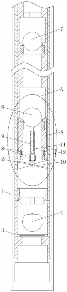
[0024] see Figure 1-7 , an oil pump for oil fields, comprising an oil well 1, a pump barrel 2 and an oil inlet chamber 3, the pump barrel 2 is fixedly sleeved with the oil well 1, the top of the oil inlet chamber 3 is fixedly connected with the bottom end of the pump barrel 2, and the oil inlet chamber A lower sealing ball 4 is movably installed inside the 3, a plunger 5 is connected to the inner movable sleeve of the pump barrel 2, ...


PUM


Abstract

The invention relates to the technical field of oil field exploitation, and discloses an oil well pump used in an oil field, which includes an oil well, a pump barrel and an oil inlet chamber, the pump barrel is fixedly socketed with the oil well, and the top end of the oil inlet chamber is connected to the bottom of the pump barrel. End fixed connection. Through the setting of the spiral scraper, the spiral scraper can remove the crude oil adhering to the inner wall of the pump barrel under the plunger, reduce the thickness of the adhered crude oil, so as to better form an oil film and reduce the crude oil adhering to the inner wall of the pump barrel The sand inside can reduce the accumulation of sand between the plunger and the pump barrel, reduce the wear of the plunger, and increase the service life of the oil well pump. At the same time, through the setting of the central shaft and the cross rod, as the plunger descends, the screw The scraper is rotated by the upward impact of the crude oil, and then drives the middle sealing ball to rotate, so that the crude oil forms a swirling flow and transmits upwards, reduces the resistance to the plunger, speeds up the transmission rate, and reduces the direct impact with the middle sealing ball, further accelerating the crude oil. transmission rate.

Description

technical field [0001] The invention relates to the technical field of oilfield exploitation, in particular to an oil pump for oilfields. Background technique [0002] The oil well pump is a kind of commonly used oil pumping equipment for pumping the crude oil in the well to the ground. Figure 8 As shown, the pumping method is to lift the crude oil from a low place to a high place through the up and down movement of the plunger 5, and pump the crude oil from the bottom of the well to the top of the well and out of the output well. pressure, the upper sealing ball 7 and the middle sealing ball 6 are closed, and the lower sealing ball 4 is pulled up, so that the crude oil enters the pump barrel 2 from the oil inlet chamber 3, and at the same time, the crude oil on the upper part of the plunger 5 is lifted. When going down, the lower sealing ball 4 is closed, and the upper sealing ball 7 and the middle sealing ball 6 are opened. As the plunger 5 descends, the crude oil at the ...

Claims


Application Information

Patent Timeline
Patent Type & Authority Patents(China)
IPC IPC(8): F04B47/00F04B53/14F04B53/16F04B53/10F04B53/12F04B53/02B08B1/00
CPCF04B47/00F04B53/00F04B53/14F04B53/16F04B53/1002F04B53/126F04B53/02F04B47/005B08B1/005B08B1/008
Inventor 刘伟
Owner 东营市三和石油装备有限公司
Why Eureka
Try Eureka