Rubber joint three-way fatigue test device based on pull rod

A rubber joint and fatigue test technology, applied in the field of rail vehicle product testing, can solve problems such as the easy wear of universal joints, the inability to fully simulate the use of ball joints, and the large error of ball joint torsional fatigue angles, etc., to improve Test efficiency and reliability, avoid test dispersion and error, reduce the effect of guide post friction

Active Publication Date: 2020-12-01
ZHUZHOU TIMES NEW MATERIALS TECH
View PDF10 Cites 2 Cited by
  • Summary
  • Abstract
  • Description
  • Claims
  • Application Information

AI Technical Summary

Problems solved by technology

The torsional force applying devices in these two test devices include two universal couplings. With the increase of service time, the universal couplings are easy to wear and cause the torsional fatigue angle error of the ball joint to increase, and the replacement frequency is high.
And with the increase of the outer diameter of the ball joint, the overall size and weight of the device increase significantly, which is not suitable for the three-way loading fatigue test of the ball joint with large outer diameter
[0007] Moreover, the test devices described in the above-mentioned patents all perform three-way loading fatigue tests on independent ball joints, but during the actual loading and operation process, the ball joints of the primary axle box tie rods, the nodes of the positioning jib and the ball joints of the secondary traction rods are all It is assembled in the rod body or the rotating arm, and the displacement motion of the rod body or the rotating arm is converted into the deflection and torsion motion of the ball joint, that is, the above-mentioned experimental device cannot completely simulate the actual loading and use of the ball joint

Method used


Image

  • Rubber joint three-way fatigue test device based on pull rod
  • Rubber joint three-way fatigue test device based on pull rod
  • Rubber joint three-way fatigue test device based on pull rod

Examples


Embodiment Construction

[0040] The embodiments of the present invention will be described in detail below with reference to the accompanying drawings, but the present invention can be implemented in many different ways defined and covered by the claims.

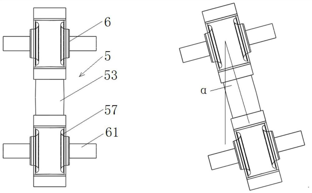
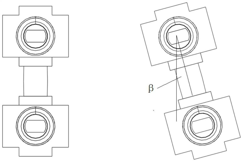
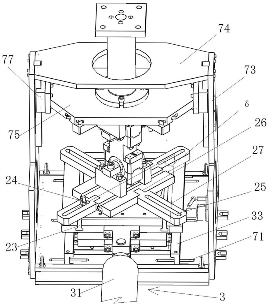
[0041] Such as Figure 1-8As shown, the embodiment of the present invention discloses a three-way fatigue test device for rubber nodes based on tension rods, including a vertical loading device 1, an angle adjustment device 2, a lateral loading device 3, a longitudinal bias device 4 and a tension rod device 5, wherein , the vertical oil cylinder 11 of the vertical loading device 1 realizes applying force to the tie rod device 5 in the vertical direction, and the angle adjustment device 2 is used to adjust the deflection angle α and the torsion angle β of the tie rod device 5, the lateral loading device 3 and the longitudinal bias The device 4 realizes applying force to the tie rod device 5 in both transverse and longitudinal directions. Pull bar de...


PUM


Abstract

The invention discloses a rubber joint three-way fatigue test device based on a pull rod. The device comprises a vertical loading device, angle adjusting devices, a transverse loading device, a longitudinal bias device and a pull rod device, the pull rod device comprises an upper connecting device, a lower connecting device and a pull rod with spherical hinges at two ends; the angle adjusting devices are mounted on the upper side of the upper connecting device and the lower side of the lower connecting device; the lower connecting device is connected with the lower end of the pull rod, the upper connecting device is connected with the upper end of the pull rod, the loading end of the transverse loading device and the adjusting end of the longitudinal bias device are connected with the angle adjusting device on the lower side, and the loading end of the vertical loading device is connected with the angle adjusting device on the upper side. By adopting the pull rod scheme, radial, deflection and torsion three-way fatigue tests of a rubber spherical hinge can be realized at the same time, tests of two spherical hinges can be performed at the same time, the test efficiency and credibility are improved, and test discreteness and errors caused by individual differences of the spherical hinges are avoided.

Description

technical field [0001] The invention relates to the technical field of rail vehicle product testing, in particular to a three-way fatigue test device for rubber nodes based on tension rods. Background technique [0002] Rubber joints are made of metal jacket, metal mandrel and rubber vulcanization, and some rubber joints also contain spacers. The rubber material used has the characteristics of reducing vibration and noise and long life. Rubber joints are commonly used vibration and noise reduction components. As a movable "joint" that can transmit multi-directional loads such as radial, axial, deflection and torsion, they are widely used in machinery, locomotives and automobiles. The main function is to achieve vibration reduction, buffering and elastic connection. In order to withstand the instantaneous impact and fatigue effects of multi-directional loads, the rubber joints must not only meet the stiffness characteristics in all directions, but also have certain fatigue ...

Claims


Application Information

Patent Timeline
Patent Type & Authority Applications(China)
IPC IPC(8): G01M13/00G01M17/08
CPCG01M13/00G01M17/08
Inventor 王金辉刘晓倩唐维张运珍陶瑶王叶青冯万盛林达文
Owner ZHUZHOU TIMES NEW MATERIALS TECH
Why Eureka
Try Eureka