

Road surface identifier generation method and device, storage medium and electronic equipment
A technology of marking and marking information, which is applied in the field of map drawing, can solve problems such as unreasonable generation of road markings, and achieve the effects of improving efficiency and scalability, improving safety, and high definition
- Summary
- Abstract
- Description
- Claims
- Application Information
AI Technical Summary
Problems solved by technology
Method used
Image

Examples
Embodiment Construction
[0081] Specific embodiments of the present disclosure will be described in detail below in conjunction with the accompanying drawings. It should be understood that the specific embodiments described here are only used to illustrate and explain the present disclosure, and are not intended to limit the present disclosure.
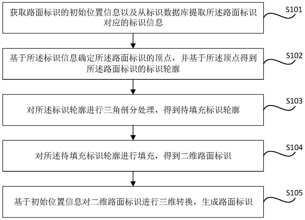
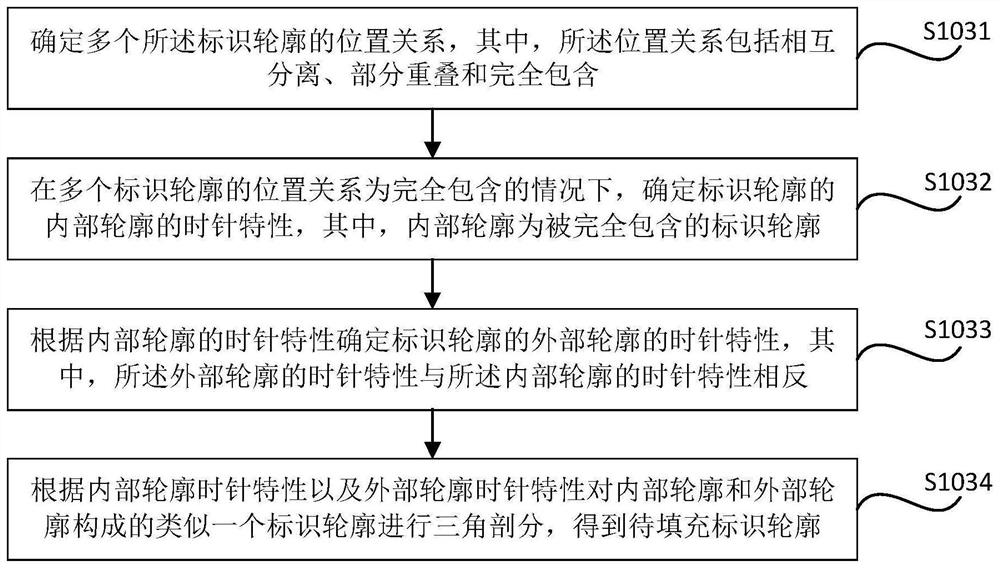
[0082] Before introducing the method and device for generating road markings, the storage medium, and the electronic device provided by the present disclosure, the application scenarios of the embodiments of the present disclosure will be introduced first. Optionally, the method for generating road markings provided in the present disclosure can be used for generating road markings in automatic driving / unmanned driving, and used in vehicle-mounted safety systems. Wherein, the road surface signs may include literal traffic signs, such as bus lanes, graphic traffic signs, such as bicycle signs, and digital traffic signs, such as deceleration signs, speed limit ...
PUM
 Abstract
Description
Claims
Application Information