Eureka AIR delivers breakthrough ideas for toughest innovation challenges, trusted by R&D personnel around the world.

Braided flat conductive tape

A conductive tape, flat conductor technology, applied in braided wire conductors, flat/ribbon cables, conductors, etc., to achieve the effect of improved packaging and low profile

Pending Publication Date: 2020-12-01
FORD GLOBAL TECH LLC
View PDF0 Cites 0 Cited by
  • Summary
  • Abstract
  • Description
  • Claims
  • Application Information

AI Technical Summary

Problems solved by technology

However, this forms a compressed structure that is no longer freely intertwined

Method used


Image

  • Braided flat conductive tape
  • Braided flat conductive tape
  • Braided flat conductive tape

Examples


Embodiment Construction

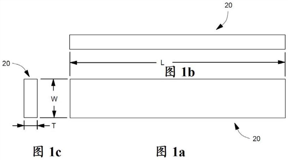
[0015] Figure 1a to Figure 1c A flat conductive strip 20 is shown in which Figure 1a shows the length L and width W of the strip, Figure 1b shows the length L and thickness T of the strip, and Figure 1c The width W and thickness T of the tape are shown. It will be noted that where the conductor is a flat strip, the thickness is much smaller than the width, which can be much smaller than the length. Such as Figure 1a to Figure 1c Such relative dimensions shown may be common for flat conductive strips 20 .

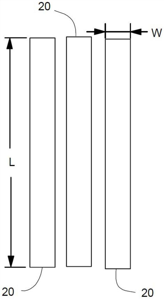
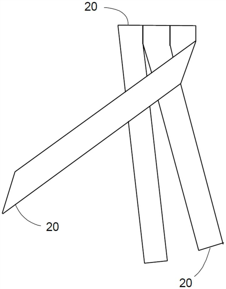
[0016] Figure 2a to Figure 2e It is shown how multiple pieces of flat conductive tape 20 are woven together to form braided flat conductive tape 22 (three pieces in this example, although there may be different numbers of flat conductive tape woven together). Because the multiple flat pieces of conductive tape 20 are woven together, each individual piece of tape can have a narrower width W than a conventional single piece of flat conductive tape could be used to ca...


PUM


Abstract

The invention provides a braded flat conductive tape. A method of forming a flat conductor that includes aligning multiple strands of flat conductive tape adjacent to each other, and braiding the strands of flat conductive tape to each other by sequentially bending one of the strands of flat conductive tape over the other strands of flat conductive tape to create a braided flat conductive tape. Each end of the braided flat conductive tape is connected to an electrical assembly for carrying electrical current therethrough.

Description

technical field [0001] The present invention relates to flat conductors, and more particularly, to braided flat conductive tape. Background technique [0002] Flat conductors such as conductive copper tape and printed / painted circuits can be beneficial when a low profile of the conductor and improved packaging are required. However, while the conductive strip is generally flexible when flexed in the strip thickness direction, the conductive strip is generally inflexible when an attempt is made to bend (bend) the conductive strip in the strip width direction. In addition to requiring some type of strain relief along the length of the conductive tape that flexes in the width direction of the tape, this disadvantage can also make it impractical to form curved conductors on the surface from the tape. Also, the belt is generally inflexible along its length. However, a flat conductor mounted on a solid surface needs to be able to withstand stresses caused by temperature changes ...

Claims


Application Information

Patent Timeline
Patent Type & Authority Applications(China)
IPC IPC(8): H01B13/00H01B13/012H01B5/12H01B7/00H01B7/04H01B7/08
CPCH01B5/12H01B7/0045H01B7/04H01B7/08H01B13/00H01B13/01254H01B7/0853H01B13/0036H01B7/0869
Inventor 加布丽埃勒·伊丽莎白·莫伊拉宁·伍尔斯特克
Owner FORD GLOBAL TECH LLC
Why Eureka
Eureka Blog
Learn More