Electromagnetic switch production method and production equipment thereof

A technology for electromagnetic switches and production equipment, which is applied to electrical switches, circuits, electrical components, etc., and can solve the problems of weak connection of pressing pieces, huge installation structure of electromagnetic switches, and difficulty in insertion.

Inactive Publication Date: 2020-12-01
李丹
View PDF1 Cites 4 Cited by
  • Summary
  • Abstract
  • Description
  • Claims
  • Application Information

AI Technical Summary

Problems solved by technology

[0004] The existing technology has the following deficiencies: 1. The rotation mode will cause the disc to deform under the force on the side station, which will affect the processing accuracy; 2. The feeding direction of the plastic seat has a requirement, and the vibration feeding is easy to get stuck and the accuracy is not high; 3. . The feeding efficiency of the magnetic ring is low, and the feeding is easy to make mistakes; 4. It is difficult to take out the tablet, and the rigid pressing tablet is easy to get stuck; 5. The installation structure of the electromagnetic switch is huge, it is difficult to insert and install, and the connection of the tablet is not firm; 6. Assembling the fixed deck It is difficult to install the outer expansion of the fixed deck, and the success rate and efficiency of the assembly are not high; 7. The spring connection is difficult, the glue connection is not firm, and the efficiency is low; 8. The electromagnetic switch blanking efficiency is low, and there are impurities inside the electromagnetic switch

Method used


Image

  • Electromagnetic switch production method and production equipment thereof
  • Electromagnetic switch production method and production equipment thereof
  • Electromagnetic switch production method and production equipment thereof

Examples


Embodiment Construction

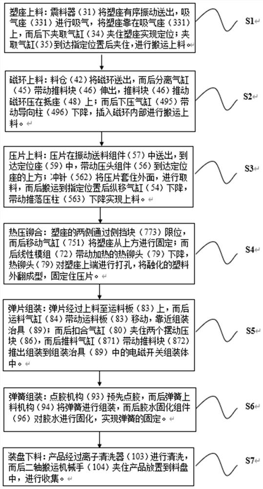
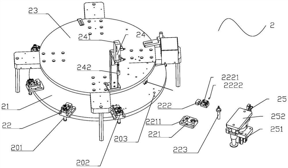
[0050] like Figure 2-16 As shown in, producing an electromagnetic switching device comprising a frame and a carousel conveying device 1 mounted on a frame 2 of plastic material seat means 3, the ring feed means 4, 5 on a tablet feeding apparatus, the linear transport device 6 , for 7, 8 fixed deck, the assembly means of the spring assembly and a cleaning means 9 melt feeding device assembly apparatus 10; carousel conveying means 2 according to the linear transport device 6 are connected, said plastic base material means 3, feed means 4 and feeding device 5 sequentially on a tablet magnetic ring disposed outside of the delivery device 2 of the turntable; hot melt packaging device 7 and the cartridge assembly fixing means 8 disposed side linear transport device 6; said linear transport device 6 is provided with a shift operation mechanism fixture 11 is assembled with the interface between the spring means 9; feeding means 10 is assembled with the spring means 9 according to the clea...


PUM


Abstract

The invention discloses electromagnetic switch production equipment. The electromagnetic switch production equipment comprises a rack and a turntable conveying device, a plastic seat feeding device, amagnetic ring feeding device, a pressing sheet feeding device, a linear conveying device, a hot melting assembling device, a fixed clamping seat assembling device, a spring assembling device and a cleaning discharging device which are mounted on the rack, wherein the turntable conveying device is connected with the linear conveying device, and the plastic base feeding device, the magnetic ring feeding device and the pressing sheet feeding device are sequentially arranged on the outer side of the turntable conveying device. The hot melting assembling device and the fixed clamping seat assembling device are arranged on the side of the linear conveying device; the linear conveying device and the spring assembling device are connected through a transferring jig mechanism. And the cleaning discharging device is connected with the spring assembling device. The turntable is efficient in conveying and accurate in machining; the plastic base, the pressing sheet and the fixed clamping base areaccurate in feeding, efficient, accurate in spring separation and firm in glue connection; and cleaning and discharging are conducted in sequence, and the product collecting efficiency is high.

Description

Technical field [0001] The present invention relates to a technical field of production of electromagnetic switch, in particular to a method of producing an electromagnetic switch and production equipment. Background technique [0002] Electromagnetic switches, as the name implies are the switches controlled by electromagnets, that is, the combination of electromagnets and switches. When the electromagnet coil is energized, an electromagnetic suction is generated, the movable iron core push or pull the switch contact, thereby connecting the control circuit. Electromagnetic switches have a wide range of applications in various industries, the most common of industrial contactors. The electromagnetic switch plastic seat ring, compression spring, and the electromagnetic coil holder with the composition; inside plastic holder is provided with a solenoid subsequent tabletting in the plastic seat ring is fixed, loaded from the side of its holder plastic seat holder with a jammed soleno...

Claims


Application Information

Patent Timeline
Patent Type & Authority Applications(China)
IPC IPC(8): H01H11/00
CPCH01H11/00
Inventor 李丹高飞飞
Owner 李丹
Why Eureka
Try Eureka